FourStar - Starserver Documentation
The Observatories of the Carnegie Institution for Science
(Carnegie Observatories), Pasadena, CA
v0.913
Christoph C. Birk (birk AT obs DOT carnegiescience DOT edu)

Location of this document:
http://instrumentation.obs.carnegiescience.edu/Software/FourStar/starserver.html
Teledyne provides a Microsoft Common Object Model (COM) library that allows the
detector control software - StarServer - to communicate with each JADE2 (and in turn
with its ASIC) via the USB 2.0 interface. The COM library uses the Teledyne Hardware
Abstraction Layer (HAL) software to interface with the USB port. The HAL is run either
as a standalone program or under the Teledyne ASIC Integrated Development Environment
(IDE) software.
Unfortunately, the standalone version of the HAL cannot be controlled
programmatically via the COM interface, requiring user action via a GUI. This would
require the FourStar software to be started manually on all four PCs. Although somewhat
awkward, we chose therefore to use the HAL included in the IDE, because the IDE may be
opened and controlled programmatically via the COM interface.
To our high-level application programs the StarServer software effectively abstracts
away the complex details of the H2RG/ASIC/JADE2 hardware. This design allows the
Control Mac (user level) software to simply use the network to communicate with the four
StarServer programs, and does not require knowledge of any low level implementation
details. The Windows PCs running StarServer also provide a data buffer to facilitate
uninterrupted read sequences and store an entire loop sequence (up to 64 exposures) in
RAM. This data is transferred asynchronously to the Control Mac.
- 1: Setup
- 1.1: IDE/HAL
- 1.2: Starserver
- 2: Operation
- 2.1: IDE/HAL
- 2.2: Starserver
- 2.2.1: Reference Pixel Subtraction
- 2.2.2: Readmodes and Array Clocking
- 2.3: User-Level Control
1 : Setup
1.1 IDE/HAL
Installing the IDE/HAL-server:
- 1. Run 'setup.exe'
- This should install the IDE + HAL-sever programs.
- If you are planning to use the IDL-code you'll have to install
IDL first, then the IDE.
- 2. Verify installation of the QuickUSB driver (re-install if necessary)
- When connecting the JADE card for the first time to the
computer's USB port there should
be a dialog box informing you about a new USB device. Sometimes
Windows wants to re-install the QuickUSB driver; just do it and
accept all default settings.
- 3. Use gacutil.exe to install halwrapper.dll into the global
assembly cache (c:\windows\assemby)
- gacutil /i halwrapper.dll
-
1.2 Starserver
- 1. If you are planning to compile the Starserver
software yourself:
- Download the VisualStudio VisualC++
Express
C-compiler or any other C-computer you are comfortable with.
- 2. Expand the starserver.tar.gz archive into the 'C:/'
partition of your computer.
- All paths are hardcoded, so please ensure the following
directory structure:
c:\starserver\         : contains the project files (.sln,.vcproj)
c:\starserver\data\    : default data directory
c:\starserver\debug\   : object-files and executable (debug-version)
c:\starserver\release\ : object-files and executable (release-version)
c:\starserver\src\     : contains the source code (.c,.h,.rc)
- When you are compiling a new version it is usually sufficient
to copy the new 'src' directory' because the project files
rarely change.
2 : Operation
2.1 IDE/HAL
- IDE version 1.x
Either
- start the IDE and press the green triangle to start the HAL, or
- start the HAL-Server and press the green START button.
- IDE version 2.x
- You may choose either of the above (v1.x) options or you may
start the IDE using the Startup HAL/IDE menu-entry of the
Starserver
GUI.
2.2 Starserver
Main Menu:
- File
- Startup HAL/IDE: IDE-v2.x allows to be started programmatically.
- Upload/JADE: Upload the JADE firmware.
This is necessary after a cold start (power-cycle) of the
JADE/ASIC hardware.
- Upload/ASIC: Upload the ASIC code. This is necessary after a
power cycle. This may be used during engineering to modify the
actual code running on the ASIC.
- Exit: Terminate the Starserver program.
- Options
- Datapath: Set the path for the FITS files.
- RefPix-Sub: Set the number of lines used referece pixel subraction
(explanation)
- PreResets: todo
- Simulator: Settings for the data simulator.
- ASIC
- Show Register: todo
- Note: Setting the channel# to '0' changes all channels.
- Gain: ASIC op-amp gain setting [0..15] (see chapter 3.4.3.3 of the
Sidecar ASIC Technical Manual).
- CC: Compensation capacitor setting [0..63] (see chapter 3.4.3.2
of the
Sidecar ASIC Technical Manual).
- Filter: ASIC output filter setting [0..15] (see chapter 3.4.4 of the
Sidecar ASIC Technical Manual).
- ??? Not sure if this one can be changed at runtime or can only
be set by the .mcd file ???
- ResetScheme: todo
- ArrayTemp: todo
- InputRef: todo
- Vref: Reference voltage [?..?] (see chapter 3.4.1 of the
Sidecar ASIC Technical Manual).
- Dsub: todo
- Vreset: todo
- Vdd: todo
- 5volt: ASIC power supply. It is recommended to turn off the
ASIC power supply before disconecting the JADE power-supply.
- JADE
- Vdd(ss)IO: todo
- Clock-Freq: todo
- Help
- Help: Opens this web-page.
- About: Shows the version, compilation date and copyright
information about this software.
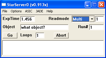
- ExpTime: Set exposure time.
- The exposure time has to be a multiple of the frame time
(1.456 seconds). For longer exposures the granulation
will be multiples of the frame time due to the insertion of
drop-frames (detailed explanation).
- ReadMode: Select readout mode
(detailed explanation).
- Reset: read reset level
- Bias: (equivalent to min. exposure time "Single")
- Single: reset, wait exposure time, read
- Double: reset, read, wait exposure time, read
- Fowler/Multi: reset, #reads, wait exposure time, #reads
- Ramp: reset, continous reads during exposure time
- The edit window to the right of the readmode is used for
Fowler sampling only. It defines the number of
Fowler pairs.
- Object: Set object name written into FITS file
- Run#: Set run number 'rrrr' in FITS file name.
- fsr_rrrr_ll.fits ('ll' is the loop number within the sequence/run)
- Go: start run (sequence of 'Loops' exposures).
- Loops: number of exposures per run.
- Abort: abort the current run.
2.2.1: Reference Pixel Subtraction
The array is readout in 32 channels that form (vertical) stripes
each 64 pixels wide and 2048 pixels high. There are 4 rows and 4 columns
of reference pixels all around the array,
R=reference pixel, D=data pixel:
      <------ channel-1 ---------> <- channel-2 ....... ch-32 ->
      1  2  3  4  5  6  7  8 .. 64 65 66 67 68 ...          2048
   1  R  R  R  R  R  R  R  R  R  R  R  R  R  R  R  R  R  R  R  R
   2  R  R  R  R  R  R  R  R  R  R  R  R  R  R  R  R  R  R  R  R
   3  R  R  R  R  R  R  R  R  R  R  R  R  R  R  R  R  R  R  R  R
   4  R  R  R  R  R  R  R  R  R  R  R  R  R  R  R  R  R  R  R  R
   5  R  R  R  R  D  D  D  D  D  D  D  D  D  D  D  D  R  R  R  R
   6  R  R  R  R  D  D  D  D  D  D  D  D  D  D  D  D  R  R  R  R
   7  R  R  R  R  D  D  D  D  D  D  D  D  D  D  D  D  R  R  R  R
   8  R  R  R  R  D  D  D  D  D  D  D  D  D  D  D  D  R  R  R  R
   9  R  R  R  R  D  D  D  D  D  D  D  D  D  D  D  D  R  R  R  R
  ..  R  R  R  R  D  D  D  D  D  D  D  D  D  D  D  D  R  R  R  R
2044  R  R  R  R  D  D  D  D  D  D  D  D  D  D  D  D  R  R  R  R
2045  R  R  R  R  R  R  R  R  R  R  R  R  R  R  R  R  R  R  R  R
2046  R  R  R  R  R  R  R  R  R  R  R  R  R  R  R  R  R  R  R  R
2047  R  R  R  R  R  R  R  R  R  R  R  R  R  R  R  R  R  R  R  R
2048  R  R  R  R  R  R  R  R  R  R  R  R  R  R  R  R  R  R  R  R
The reference pixel subtraction scheme uses a 3 pass process
and has 1 adjustable parameter: #ref-pixel-lines.
For each channel calculate the average/median of the top 4 rows and
bottom 4 rows, ie, 64x4 pixels for each top and bottom.
Then caluclate the average of the 2 medians and call it
channel_offset.
For each row (1..2048) determine the
current (time variable) line_offset by
calculating the median of the 4 reference pixels on
the left (column1..4) and right (column-2045..2048)
subtracting the appropriate channel_offset
(ie. from channel-1 or channel-32 respectively).
Loop over all data pixels (rows/columns 5..2044) and
subtract the appropriate channel_offset and
the average of the line_offsets for the
#ref-pixel-lines nearest lines.
Eg. if #ref-pixel-lines is set to '3' we subtract
the average of the line_offsets from the current
line and the lines above and below.
This process leaves the references pixels unchanged.
2.2.2: Readmodes and Array Clocking
The array is continuously clocked by the ASIC. While in
idle mode
(non-exposure) this clocking constists either of resets
or reset+read cycles. The Starserver software
currently uses the reset only idle mode.
Whenever an exposure is started (using the Go button
on the GUI or by remote command), the Starserver program uploads
the new clocking parameters into the ASIC and waits for data
from the JADE card. After the ASIC receives the new clocking
parameters is finishes the current idle cycle and
then starts the new exposure cycle(s). Each exposure is
defined by 4 parameters:
- # resets (X)
- The number of resets (X) is currently fixed to 1.
This may change in a future version, but would increase
the time used by each exposure. It is possible to read
the array while resetting. This feature is used by the
Reset readmode.
- # reads (R)
- The first read frame immediately follows the
last reset and so does each of the R read frames.
Each read frame sends 2048x2048 pixels to the JADE buffer.
- # drops (D)
- The first drop frame immediately follows the
last read and so does each of the D drop frames.
The only difference between a read and drop
frame is that the drop frame does not send any data.
- # groups (G)
- The number of groups defines how often the read and
drop sequence is repeated. If G is larger
than one (1) then the next read frame immediately follows
the last drop frame.
Each of the frames (reset, read, drop) takes
the same amount of time, called the frame_time.
There are overheads per row and per frame, so the
frame_time becomes:
Tf = [(NC+7) * (NR+2) ] / JADE_Clock = 1.4555 sec
with NC=64, NR=2048 and JADE_Clock=100 kHz.
Every exposure follows the same scheme that is hard-coded in
the ASIC firmware:
X+G*[RD].
The exposure time (Te) must be a multiple of the group
time (Tg = Tf*[R+D]).
There are two limiting factors that determine the number of
drop-frames.
1) The size the JADE FIFO buffer (4 frames). Since the readouts
follow each other without any time in-between we try to avoid
more than 4 read-frames in a row (not possible for
Fowler sampling).
2) The size of the computer memory. Since all read-frames
are (temporarily) stored in the PC RAM, we limit the number
of read-frames to 64.
- Reset
- X=1, R=0, D=0, G=1
- The Reset mode is the only mode that has the
'readout-while-reset' bit set.
The resulting data is in the range {0..65535}.
- Bias
- X=1, R=1, D=0, G=1
- A Bias exposure is a reset immediately
followed by a read.
The resulting data is in the range {0..65535}.
Note: This is just a special case (D=0) of the Single readmode.
- Single
- X=1, R=1, D=*, G=1
- The Single readmode can have a delay
between the reset and read frames.
The resulting data is in the range {0..65535}.
- Double (special case of the Fowler readmode with F=1)
- X=1, R=1, D=*, G=2+
- Example(Te=1.456): X=1, R=1, D=0, G=2
X-R-R
- Example(Te=4.367): X=1, R=1, D=0, G=4
X-R-R-R-R
- Example(Te=8.733): X=1, R=1, D=1, G=3
X-RD-RD-RD-RD
- Fowler (generalized case of the Double readmode with F>1)
- X=1, R=F, D=*, G=2+
- Example(F=4,Te=5.822): X=1, R=4, D=0, G=2
X-RRRR-RRRR
- Example(F=6,Te=20.377): X=1, R=6, D=1, G=3
X-RRRRRRD-RRRRRRD-RRRRRRD
- Ramp (not used by FourStar)
- X=1, R=1, D=*, G=Te/Tg
- Example(Te=2.911): X=1, R=1, D=0, G=3
X-R-R-R
- Example(Te=11.644): X=1, R=1, D=1, G=5
X-RD-RD-RD-RD-RD
-
Note: All FITS files written by the FourStar software
(Starserver or StarGUI) use the BITPIX=16 (16 bit signed integer)
format. To accomodate the largest usefull data-range we use the
FITS keyword BZERO to adjust the zeropoint of the 16-bits
values.
With raw_value as the 16-bit signed integer in the FITS file:
real_value = BZERO + BSCALE * raw_value
With BSCALE=1.0, and BZERO=31768 the effective data range for
FourStar FITS files is -1000..64535. This appears to be a
good compromise (although it might change in the future), since
it is unlikley to have meaningful data outside that range.
2.3 User Level Control (Mac software)
The Starserver software will usually be remote controlled by the
FourStar control software, running on an Apple/Mac computer.
Please refer to the FourStar
StarGUI
software manual.
2009-04-14,
Christoph C. Birk,
Carnegie Observatories (last updated 2011-09-07)