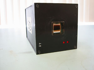
In order to use guide stars which are as faint as possible, the guider camera must have high quantum efficiency, and low read-noise. A frame transfer architecture is required to allow the guide star to be almost continuously monitored, and to provide shutterless operation. It must also be possible to calibrate the device easily and readily integrate it into the optical system.
The guider camera uses a low-noise frame transfer CCD with a digital signal processor (DSP) based CCD controller. A block diagram shows the various parts of the sensor system. The controller provides bias voltages, three phase clock signals to the parallel and serial registers, signal processing to extract and digitize the CCD output signal, and a fast serial interface to a host computer. The DSP directly generates the sequences used to clock the serial and parallel charge transfers on the CCD. Extra clock lines are provided for frame transfer. The DSP also controls the dual-slope integrator, the analog-to-digital conversion, and the data transfer to the interface card.. The design of the dual-slope integrator and clock drivers are optimized for fast settling time.
 |
 |
Physically, the guider camera consists of six circuit boards
- CCD header board with preamps
- DSP timing generator board
- Signal processing board
- Clock driver board
- Power supply board
- Backplane board
Greg Burley (burley@obs.carnegiescience.edu)
Ian Thompson (ian@obs.carnegiescience.edu)