Alignment strategy and focal plane assembly
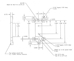
Each CCD is mounted by SITe onto a gold-coated invar substrate and held in place with an epoxy. The ccd surface is flat (to 20 µm peak-to-valley), but the epoxy layer may be uneven, resulting in an overall tilt of the ccd surface with respect to the package of 100 µm or so. The rows and columns of the ccd are only nominally aligned to the package. The packages come with four drilled and tapped mounting holes, and are tapered normal to the active surface of the detector to allow assembly of the devices in mosaics. With some care, the detectors are buttable on three sides.
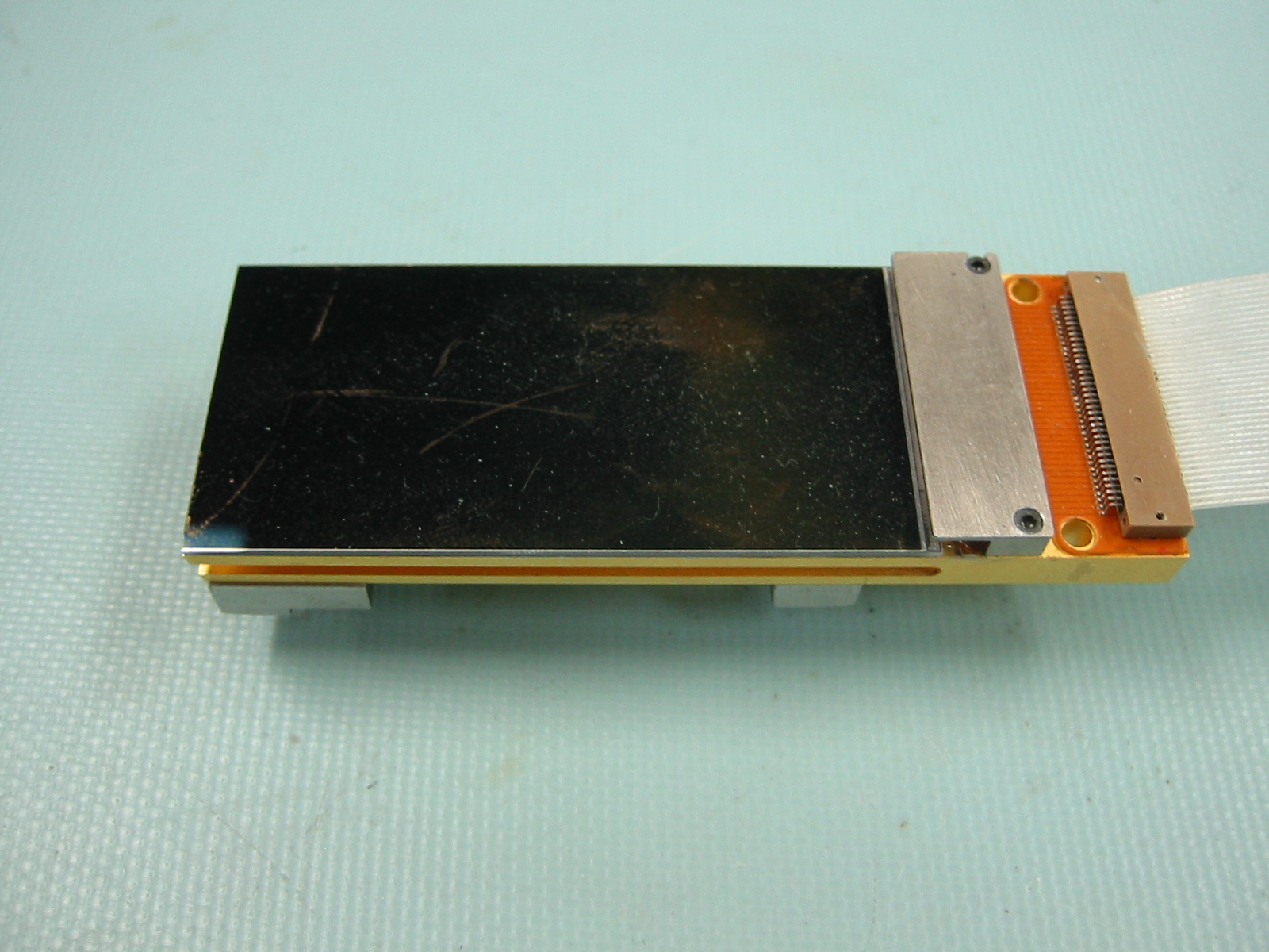 CCD+boat top view |
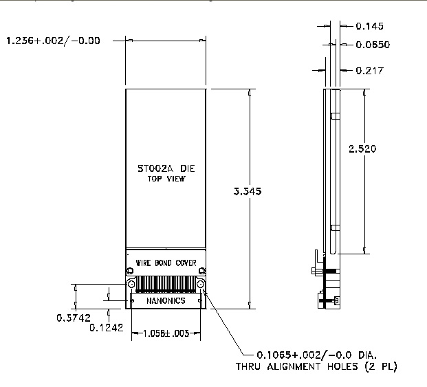 CCD mechanical drawing |
The challenge of assembling the mosaic is to take out the overall tilt of each ccd, as well as any height differences between the ccds. The rows and columns need to be aligned as well as possible (although that step is not critical for most astronomy applications). The final assembly of all the ccds onto a common substrate (aka "platten") should give a composite mosaic device that is co-planar and well-aligned.
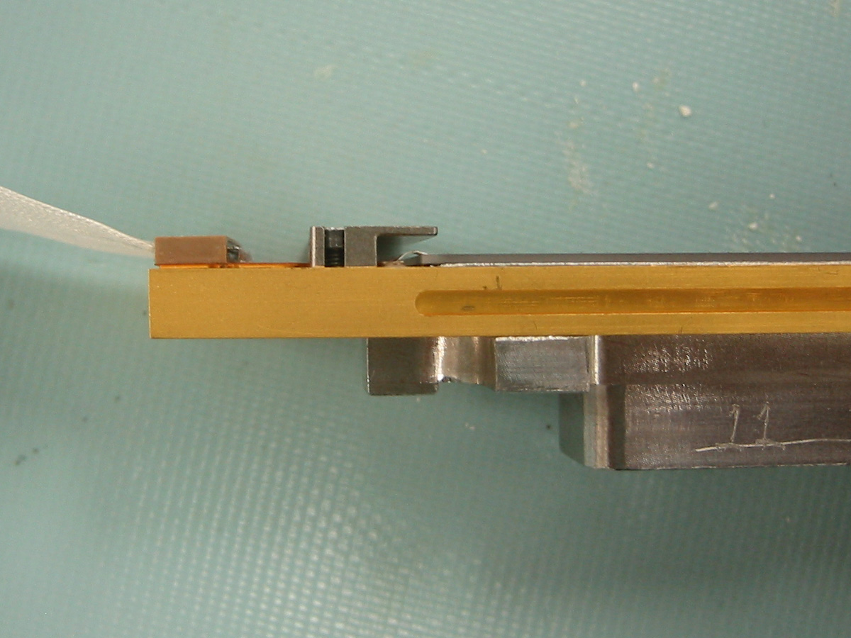
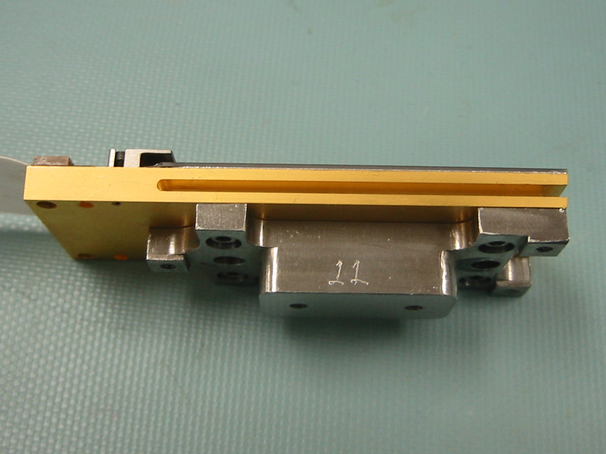 CCD+boat side view |
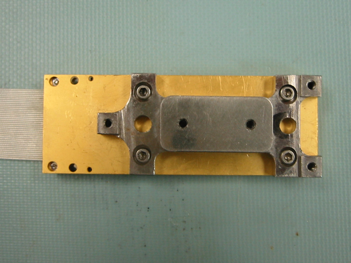 CCD+boat backside view |
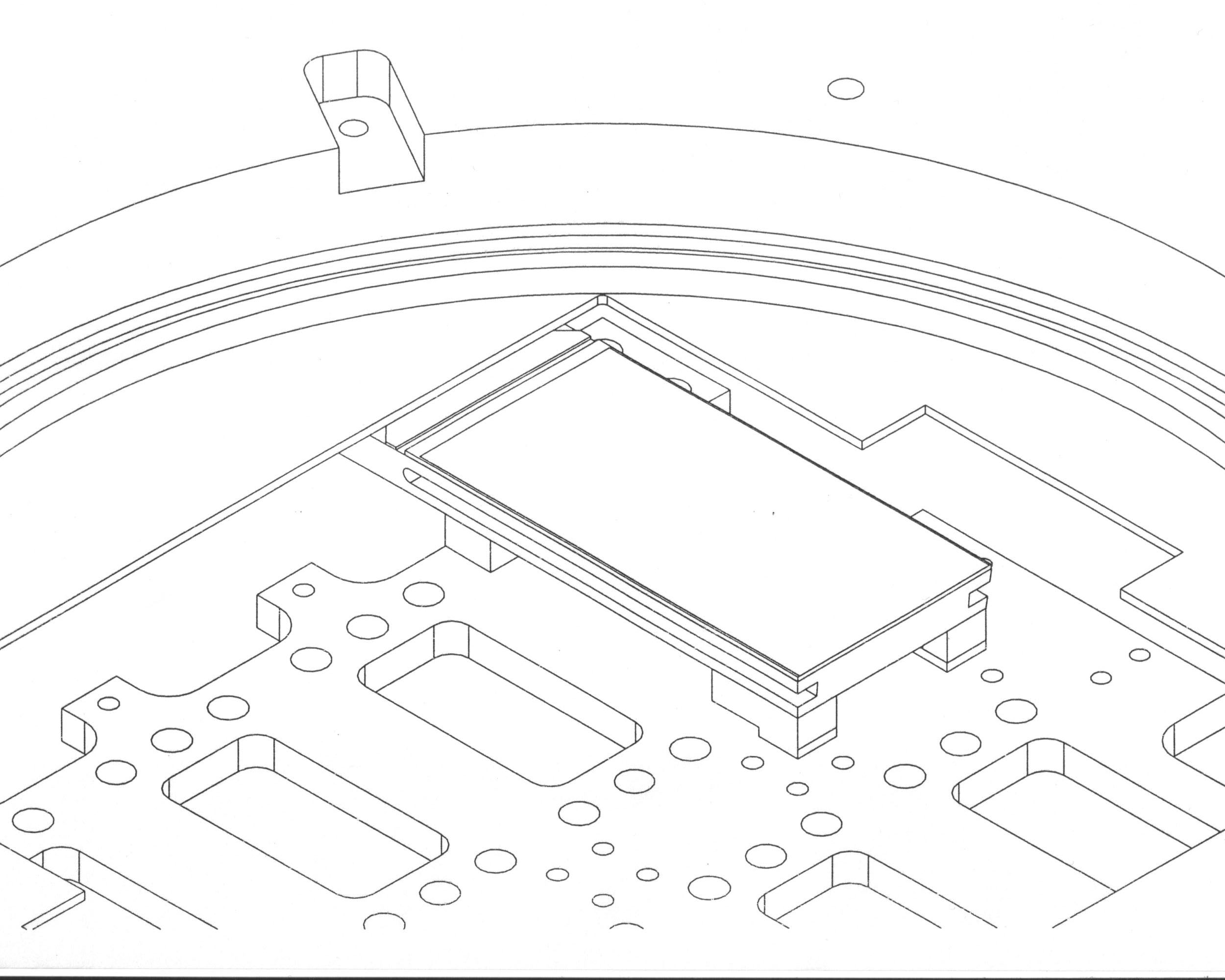
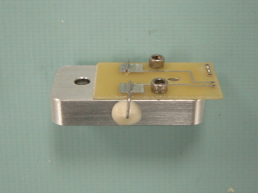
Each ccd is mounted to an invar module (aka "boat") using the four 4-40 screw holes on the back of the ccd package. The boat consists of three feet which contact the platten, two precision locating holes, and a plug which protrudes through the platten to attach to cooling straps. The three feet are designed to be ground and polished to adjust the overall height and tilt of the ccd surface. The precision locating holes join with pins on the platten. Each boat was CNC-machined, then lapped on the top surface, where it mates up with the corresponding ccd.
 CCD side profile |
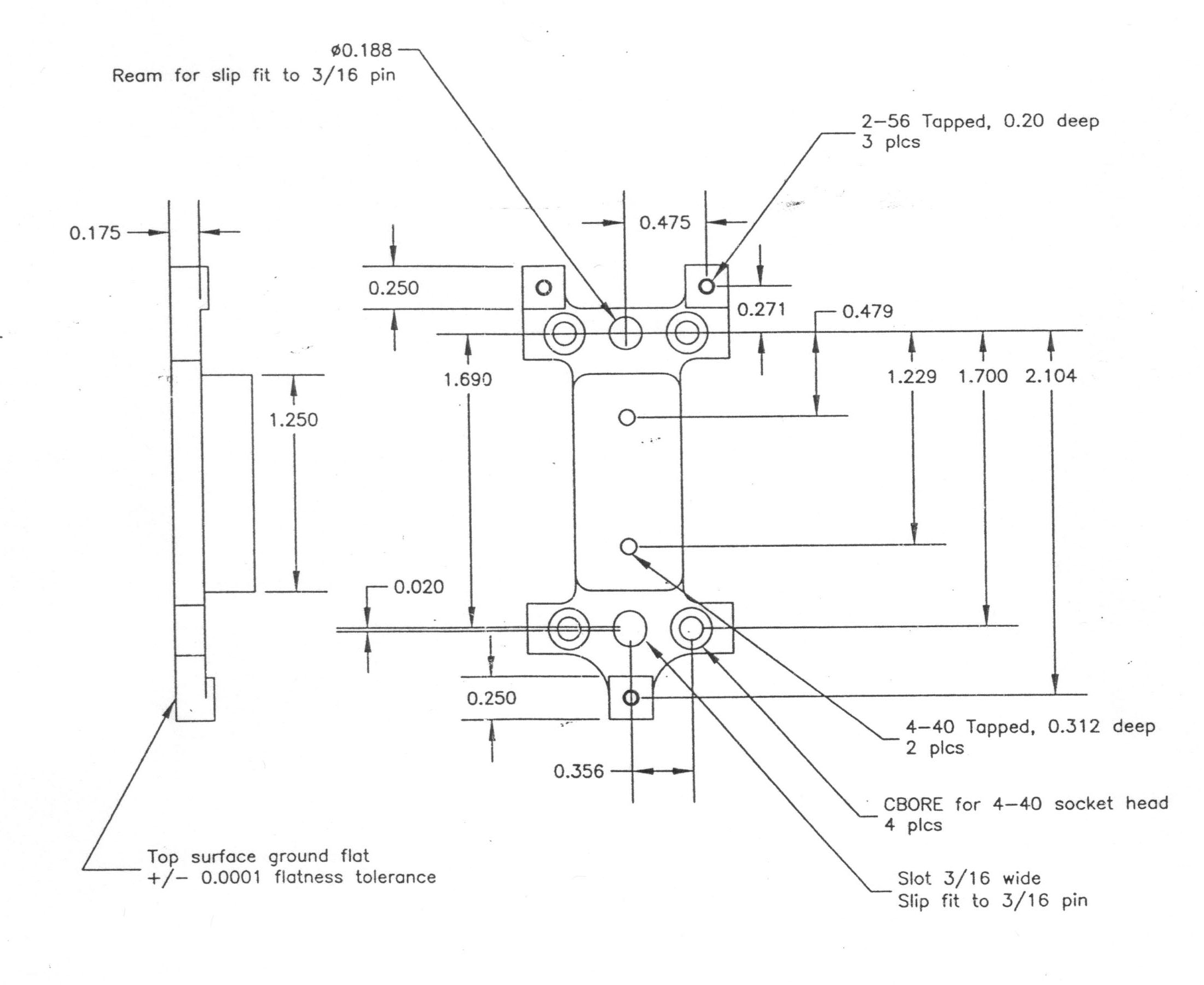 Mechanical drawing of boat |
As an additional step, the two socket head screws holding the wire-bond covers in place were counterbored to reduce the profile of the package.
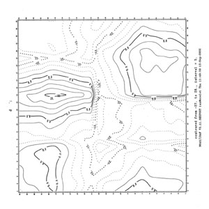
The surface profile (height and tilt) of each of the ccds was measured using a Keyence laser displacement sensor and a computer controlled x-y stage (see below). By iteratively grinding or sand-papering the feet of each of the boats, and repeatedly re-measuring the surface profiles of the ccd+boat modules, we were able to remove the overall tilt and height differences of the eight chips to within a few microns. The sandpaper grades of choice were #600 and #6000 grit.
[table of overall tilts and heights]
The final alignment of each ccd+boat module was done with a micrometer equipped jig, and the laser sensor (which has a confocal video microscope). With the boat pinned in place, the micrometers were used to nudge the rows and columns of the ccd to align with reference marks on the jig, as measured using the microscope. The four screws into the back of the ccd were tightened against belleville washers to hold the assembly together. The eight CCD+boat units were aligned to within 0.5 pixels over 4096 pixels.
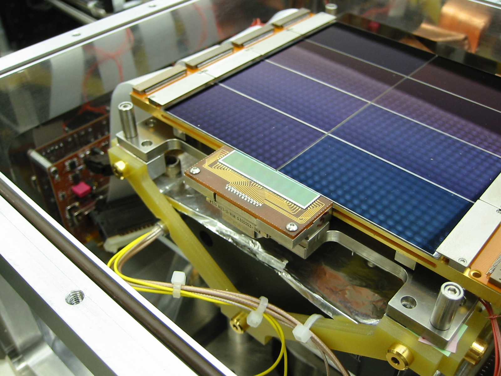 Assembled mosaic with wing chip |
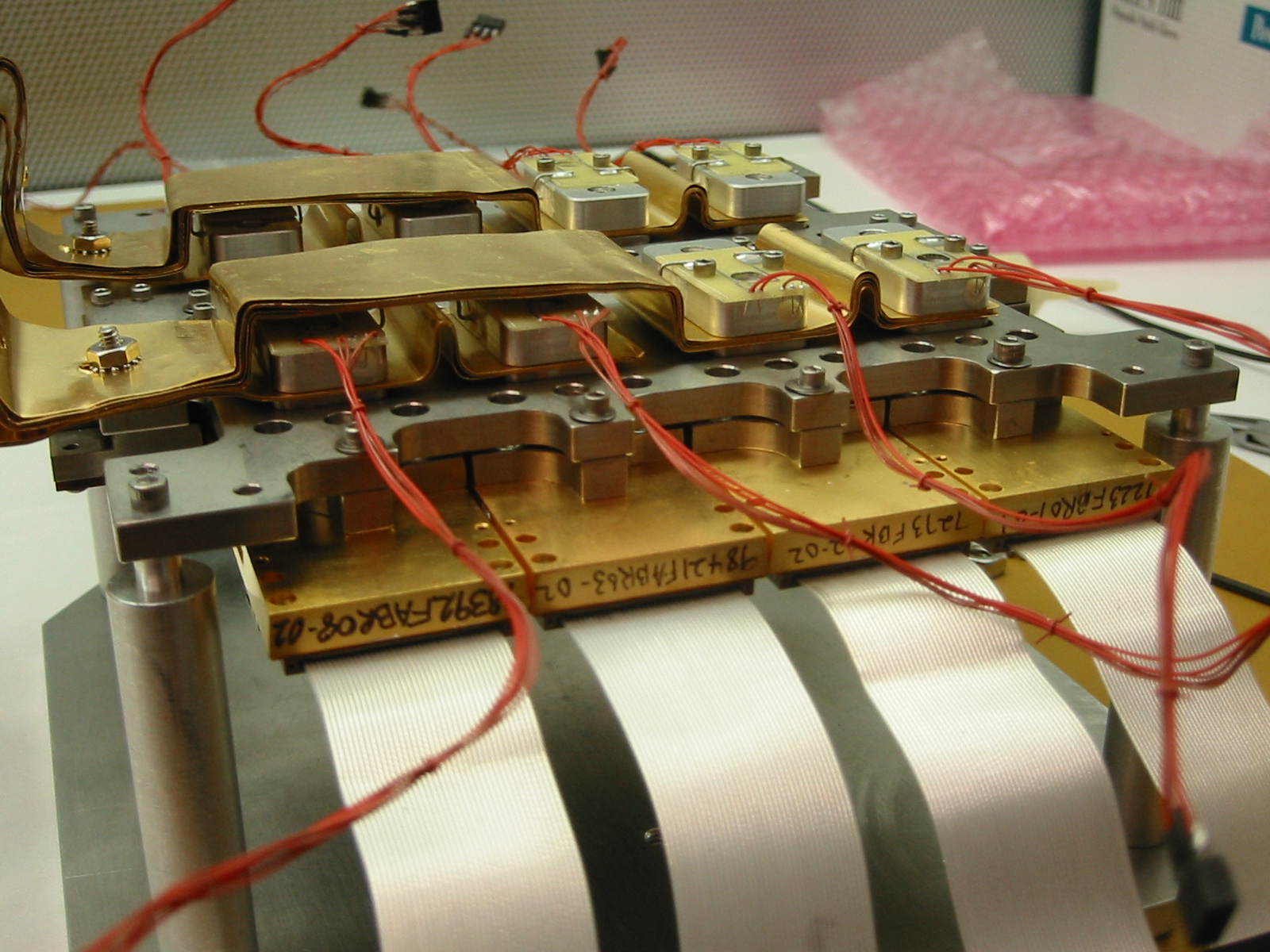 Backside of the assembled mosaic |
 Platten + ccd arrangement |
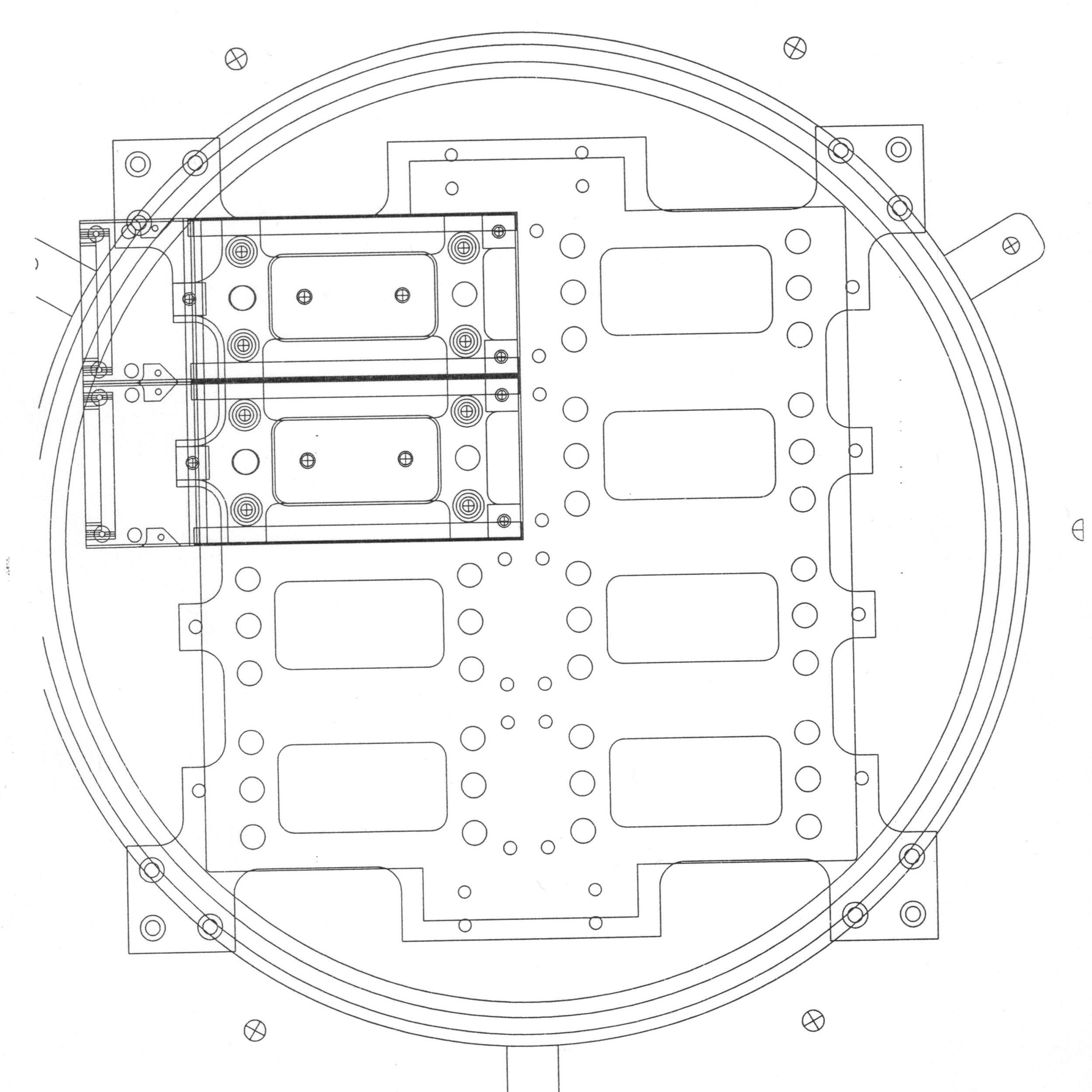 Mechanical drawing of platten |

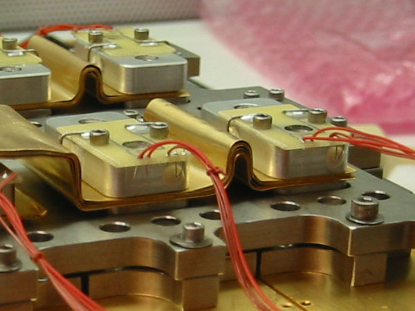
Electrical connection to each detector is made via a 3-inch long ribbon cable assembly. Normally, one might expect the ccd ribbon cable to connect directly to the preamp board. But, the ribbon cable is made of 30-gauge copper wires and is a good thermal conductor. To thermally isolate each ccd, we put a 2-inch flex cable between the ccd ribbon cable and the preamp board.
On the back of the platten, the copper cooling straps are connected to the bottom of each boat and held in place with a small aluminum block. That block contains a 20 ohm 1/4 watt heater resistor, and a platinum RTD temperature sensor. The RTD and heater resistor are connected to the preamp through a constantan wire bundle.
 Temperature sensor + heater resistor |
 Cold straps + heater/sensor blocks |
| Measured |
Required |
Goal |
Units |
|
| Flatness |
30 |
32 |
26 |
µm
P-V |
| Gap |
0.9 |
1.0 |
0.5 |
mm |
| Alignment |
100 |
1000 |
100 |
ppm |
Lab test and measurement setup
 Keyence LT-8110 confocal sensor (displacement sensor + video camera) |
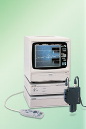 Keyence control unit |
In conjunction with a precision XY motion stage, the Keyence sensor can perform non-contact height measurement over the full surface of the mosaic. The lab setup uses a Keyence LT-8110, which includes a confocal displacement sensor and an integrated ccd video camera. The sensor head requires an LT-8105 controller, and a LT-V201 ccd controller camera unit.
The LT-8110 displacement sensor has a resolution of ±0.2 µm over a range of ±1 mm at a standoff distance of 28 mm. The beam wavelength is 670 nm and forms a red spot of 7 µm diameter (see Keyence web site for technical details).
The NEAT XY8080 precision grade stage measures 8 × 8 inches. The range of motion is 6 inches in each axis. Each stage has a Renishaw RGH22 encoder with an resolution of 1.0 µm. We use the NEAT-320 series motion controller electronics to drive the stages.
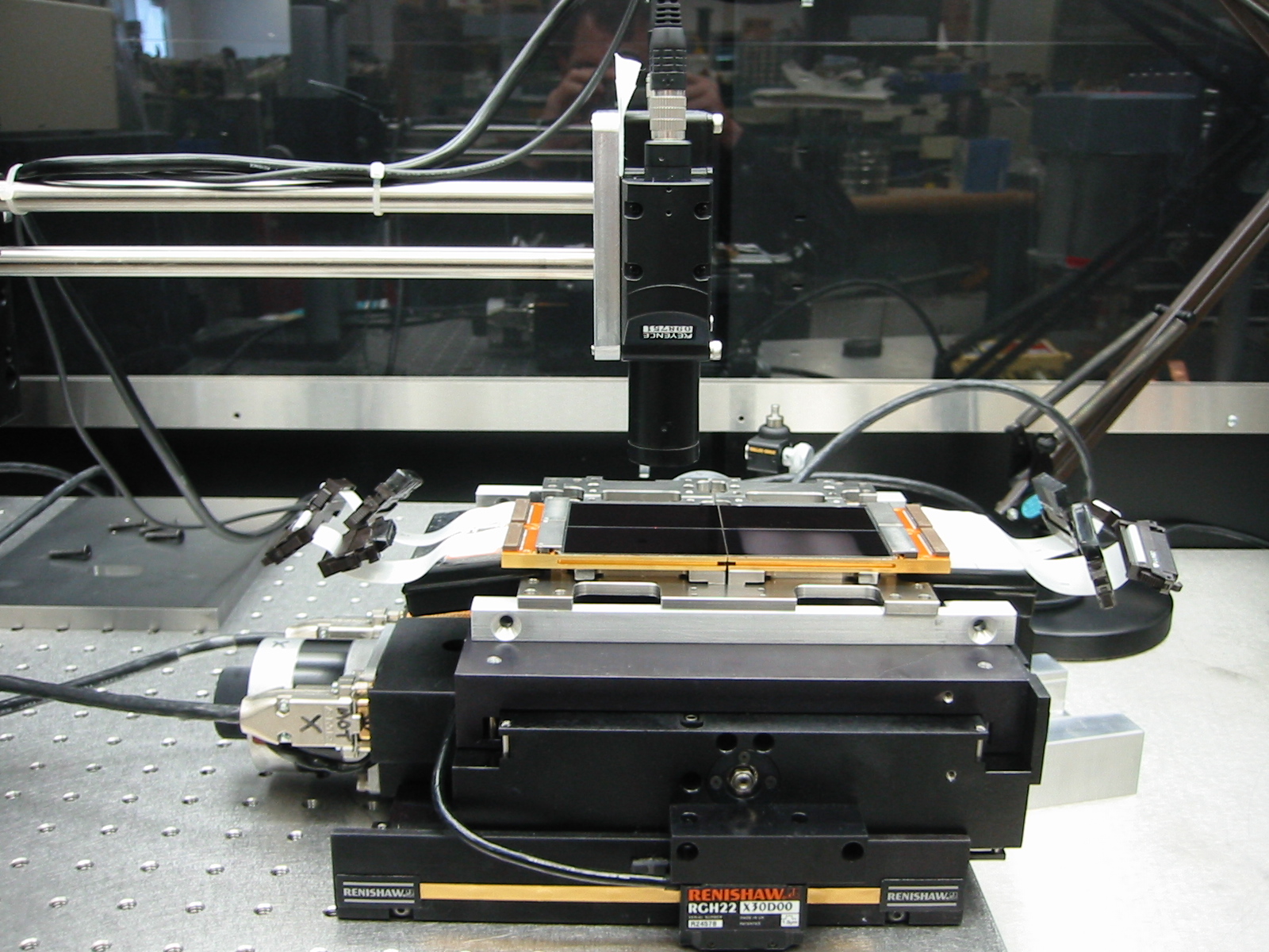 LT-8110 + NEAT stages |
Both the NEAT stages and the Keyence sensor are connected to a PC serial port and driven under program control. For each CCD surface profile, a grid of 12 × 24 measurements is used. The displacement sensor is held in a fixed position above the CCD+stages, and the CCD is moved beneath the beam. At each grid position, the stages stop, the sensor stabilizes and begins measuring and averaging. Typically, each recorded measurement is the average of 128 individual measurements.
For aligning the rows and columns of the CCDs, we used the 90X magnification video microscope built into the Keyence sensor, and a custom built alignment jig (see photo). The micometers in the alignment jig allow the CCD to translated and rotated with a fine degree of control. The location of features on the ccd are determined by spotting them with the video microscope and displacement sensor, then recording their x-y positions as determined from the Renishaw encoders.
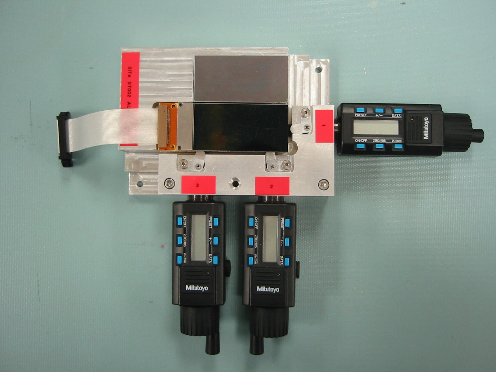 Alignment jig |
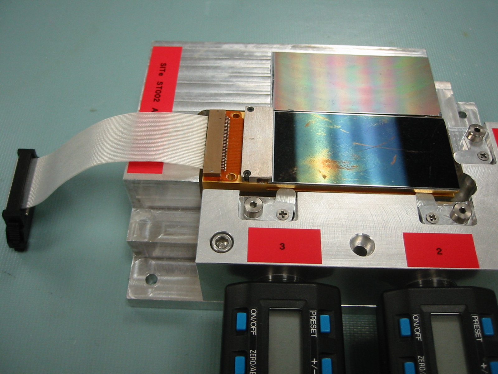 Alignment jig |
When each CCD is inserted into the alignment jig, the locator pins on the jig fix the boat into position. The CCD is pushed around using the micrometers until it is aligned with respect to the dummy ccd on the jig. Then, the screws from the boat to the ccd are tightened against Belleville washers to fix the CCD in position. When the CCD is mounted on the platten, the locating pins ensure that the rows and columns of the pre-aligned CCDs line up.