CCD Support Assembly
 Support assembly stack-up |
 Flexure + G-10 truss + piezo stage |
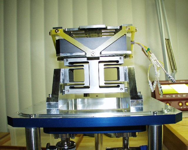
The detector array assembly, including the dewar bottom plate, can be seen in the photos. Starting at the bottom, the assembly includes the stepper-motor and worm-gear focus drive, the focus ball-screw with vacuum bellows, the focus flexure mounting legs, titanium focus flexure, flexure compensation stage, thermal isolation truss, and CCD mosaic.
The focus drive consists of a Phytron model ZSS 32.200.1.2 stepper motor (200 pulses/ revolution), a Berg 50:1 anti-backlash worm gear reducer (W48S-3S and AW48BS21-S50), a BSA MRB0802 2mm-lead ball-screw, and a stainless steel bellows which allows the moving parts of the focus system to remain outside the vacuum. The focus drive assembly attaches via an interface plate to the bottom of the titanium focus flexure.
The flexure is based on previous UH Institute for Astronomy flexure design, allows 2-mm of focus stroke, while remaining acceptably stiff against translations in the plane of the detectors, and against out of plane tilts. The flexure is a single piece of 6AL-4V titanium, which was electronic discharge machined (EDM) to produce the very deep flexure blades.
Mounted on top of the focus flexure, through a second interface plate, is the image motion compensation stage, a commercial translation stage supplied by Physik Instrumente. The motion stage, a Physik Instrument model P-527.2C, is a vacuum rated, piezo driven motion stage with capacitive position sensing. An E-500 series 2-axis, low-voltage PZT, closed-loop controller operates the motion stage and communicates with the instrument computer via a RS-232 serial link. The motion stage provides ±100 µm of X,Y stroke in the plane of the CCD mosaic, which corresponds to approximately ±6 pixels of image motion compensation.
Attached to the moving side of the PI motion stage, another interface plate serves as the base for the G10 fiberglass-composite truss which supports the CCD mosaic. The truss not only mechanically supports the mosaic, but also provides thermal isolation between the warm dewar and the cold detector mosaic.
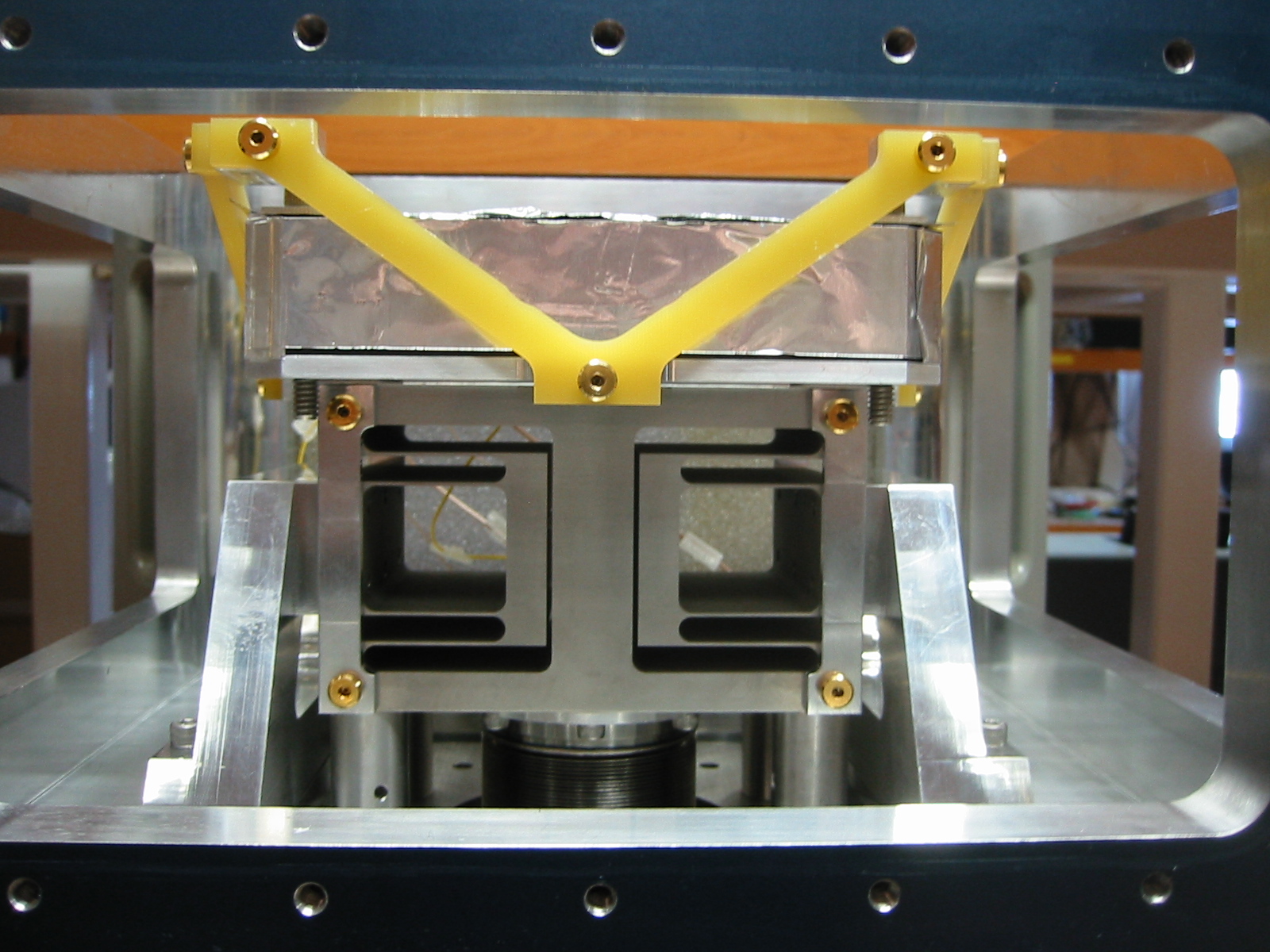
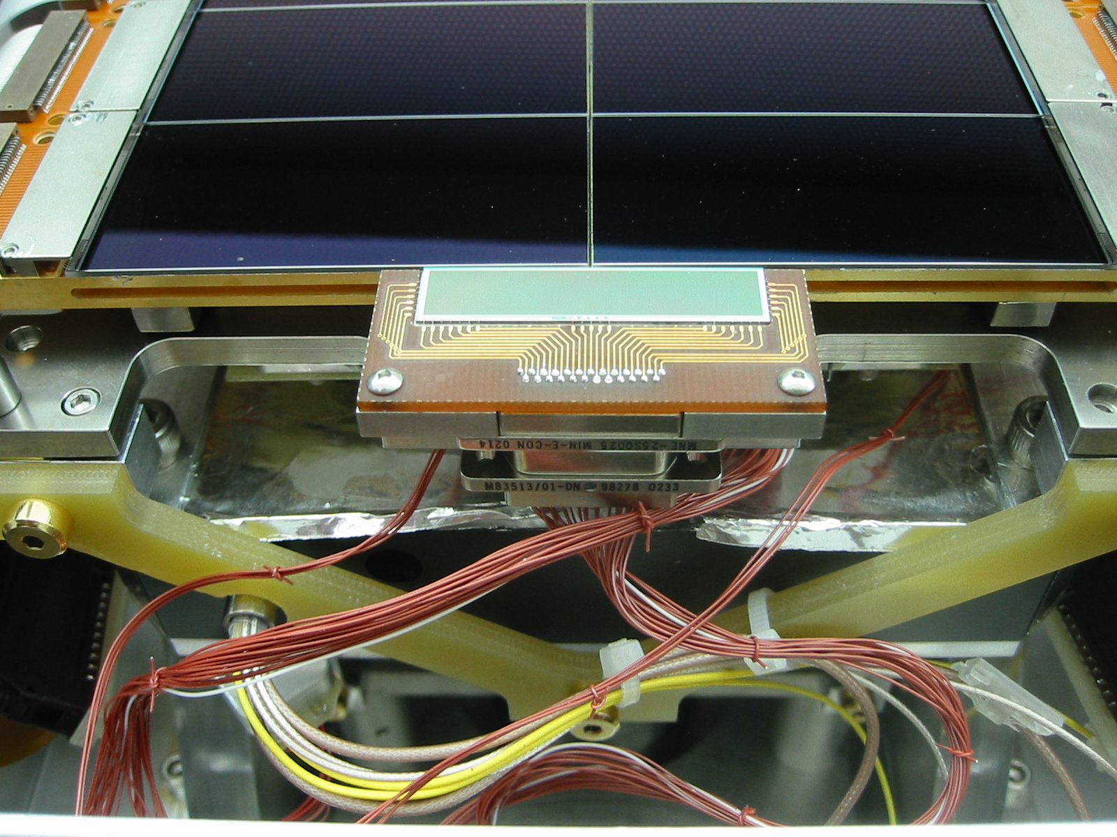 CCD array + wing chip |
The mosaic baseplate or platten is supported by the G10 truss, and in turn supports the eight science detectors and two flexure sensing wing detectors. The platten is made of Invar, to match the Invar CCD packages. The platten was ground and lapped to provide an optically flat mounting surface for the CCDs. Small interface blocks between the platten and the G10 truss were shimmed in order to bring the mosaic plane perpendicular to the dewar’s optical axis.
| Measured |
Required |
Goal |
Units |
|
| Flexure control -- X,Y
translation |
±80 | ±75 |
±150 |
µm |
| Focus control -- Z |
±1.25 | ±1.0 |
±2.0 |
mm |
| X,Y resolution |
0.1 | 0.150 |
µm |
|
| Z resolution |
0.2 |
1.5 |
µm |
|
| X,Y stability (180 deg
rotation) |
0.1 |
±0.75 |
µm |
|
| Z stability |
-- |
±1.6 |
µm |
Dewar Assembly
 Open dewar with array |
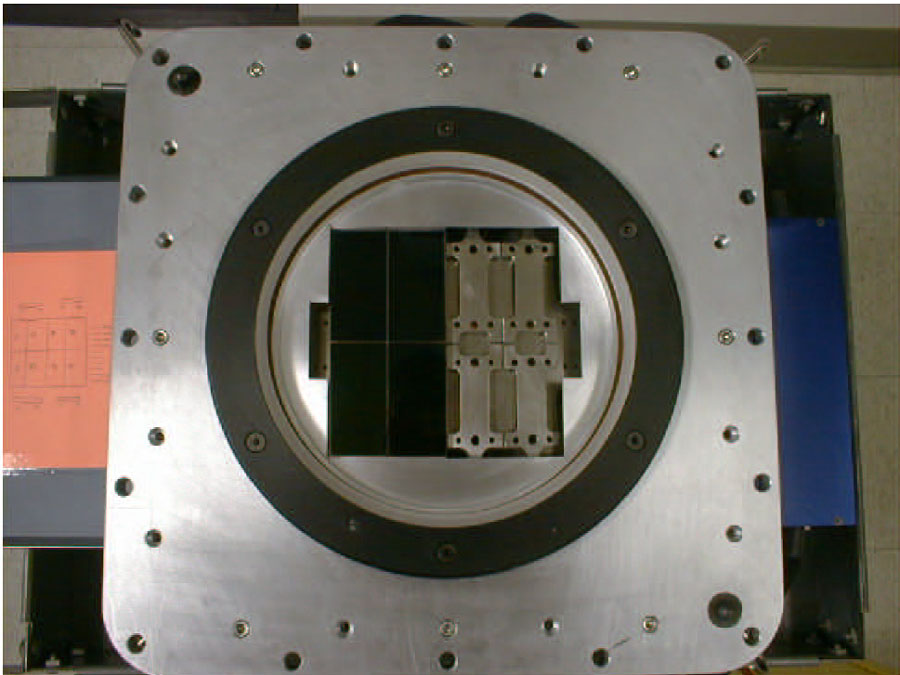 Half-filled array |
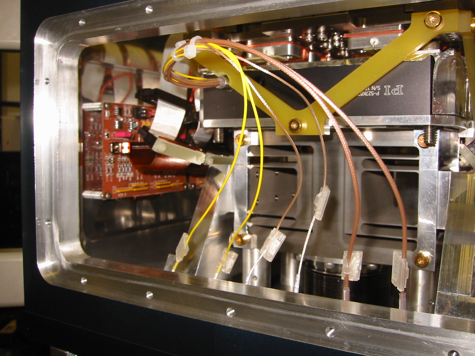 Dewar open side |
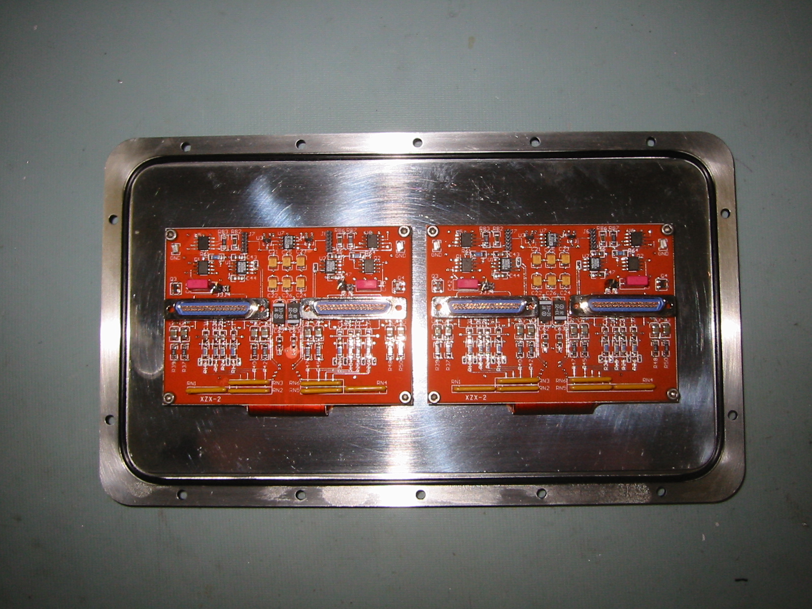 Dewar side plate with preamps |
The IMACS dewar vacuum vessel is based on a standard GL Scientific design, which has been used in various other instruments. The body of the vessel is roughly a hollow cube which was machined from a single ingot of 6061-T6 aluminum. The body of the dewar is polished on the inside to minimize emissivity, and blue-anodized on the exterior for appearance and to prevent corrosion.
The body has six apertures – two large mounting faces with o-ring grooves for the front and bottom plates, and windows on the four remaining sides, also with o-ring grooves and mounting hole patterns, for attaching the side plates. The side plates are also aluminum. Three of the four carry hermetic connectors for passing signals between the detectors and the array controller, and one carries the mounting plate for the twin cryo-coolers.
The front plate includes the mounting hole pattern for connecting the dewar to the optical cameras, and the mounting features for the dewar window, a plano-concave lens that also serves as the final, field-flattening lens in the optical train of both cameras. Indexing pins on the front plate allow the dewar to be mounted repeatably to 50 microns on the two optical cameras, and the dewar may be rotated by 90 degrees on either camera in order to orient the long gaps in the mosaic in the dispersion direction for spectroscopy.
The dewar bottom plate serves as the base for the detector mosaic assembly, and includes vacuum feed-throughs for the flexure control stage piezo actuators and capacitive displacement sensors. Also attached to the dewar body are the four over-centering latches which attach the dewar to the cameras, and lifting eyes in the plane of the dewar’s center of gravity.
The dewar body, side plates, and cryo-cooler mounts were fabricated by Ampersand Precision. The various parts of the dewar body can be seen in the photos.
The dewar is vacuum-pumped through a MDC KAV-050 Angle Valve, and vacuum level is measured with a Granville-Phillips Convectron 275 sensor and Convectron 375 Controller.
Electrical and Mechanical Interfaces
The mechanical interfaces to the dewar assembly are the following:
- Mounting flange to cameras
- Cryotiger supply/return lines
- coolant lines for ccd electronics heat exchangers
- vacuum pumping flange
- CCD signals for science detectors [four 79-pin connectors]
- CCD signals for flexure detectors [one 79-pin connector]
- vacuum pressure sensor
- flexure control signals to piezo stage
- focus drive control signals (drive motor + home/limits)