 The
LDSS CCD detector
system uses a 4064 × 4064 back-illuminated device,
with 15 µm pixels and four output amplifiers. The
CCD is an STA0500A
detector, designed by STA,
fabricated by Dalsa,
and
post-processed at ITL.
The
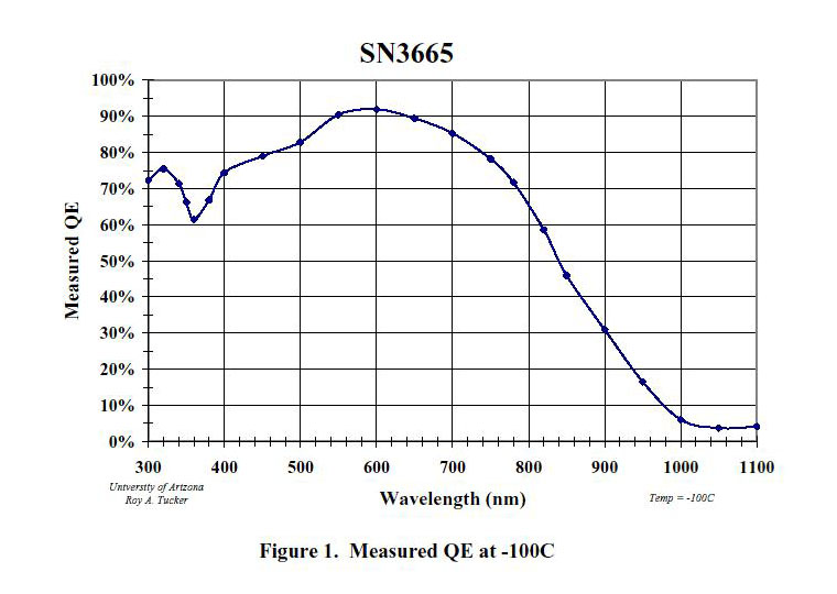
STA0500A has a broadband AR coating. The detector
is mounted in our standard single-chip rectangular aluminum housing.
The
LDSS CCD detector
system uses a 4064 × 4064 back-illuminated device,
with 15 µm pixels and four output amplifiers. The
CCD is an STA0500A
detector, designed by STA,
fabricated by Dalsa,
and
post-processed at ITL.
The
STA0500A has a broadband AR coating. The detector
is mounted in our standard single-chip rectangular aluminum housing.The CCD housing is coupled to an IR-Labs ND-2 cryostat, with the CCD control electronics box attached to the side of the dewar (see photo). The CCD is cooled to a nominal -110 C using a cryotiger closed-cycle cooler. Inside the housing, the CCD is connnected to a rigid-flex preamp board, which brings the signals out on a flex cable to a hermetic connector.
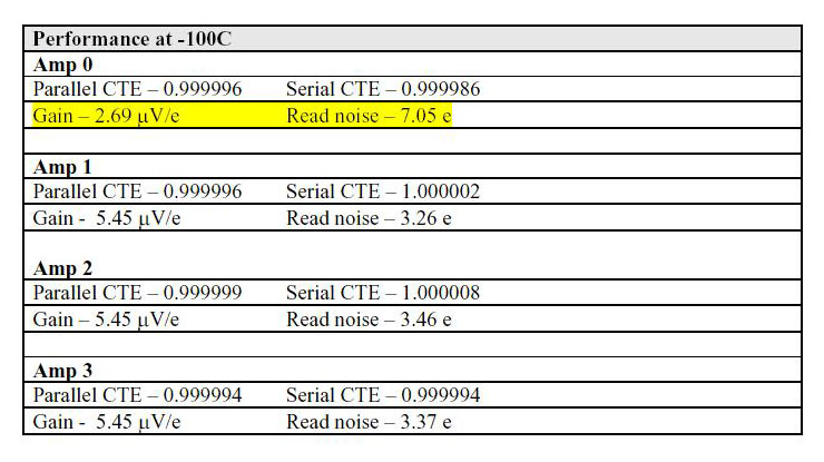
The CCD controller is a compact four-channel digital signal processor based system, capable of both high-speed and slow-scan readout. We plan to operate in slow-scan mode, using all four of the CCD output amplifiers for the lowest noise performance. Lab tests show that read noise is about 3.5 e-/pixel. The detector system is mounted horizontally on the instrument (see photo).
Update: the CCD is only capable of operating with two amplifiers, due to a charge trap in one of the serial registers.
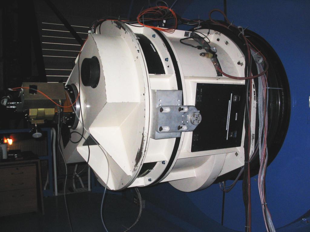 CCD System on LDSS III Dewar & electronics |
CCD Dewar & electronics |
CCD
Detector Properties
|
|||||||||||||||||||||
 |
|||||||||||||||||||||
 |
|||||||||||||||||||||
 |
Dewar Mechanical Internals
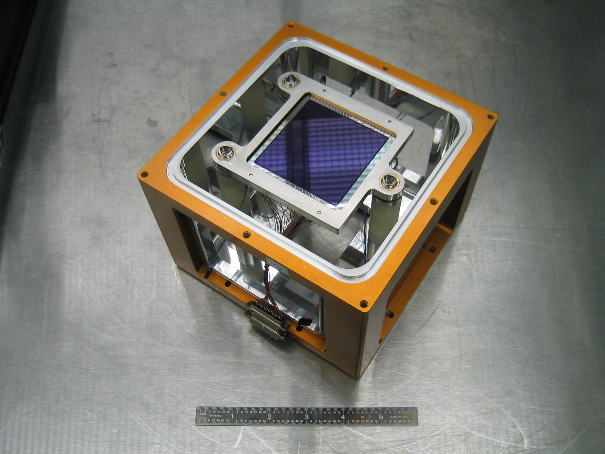
The housing for the STA0500A detector is machined from a block of aluminum, and measures 6.625 inches × 6.625 inches × 5 inches deep (see mechanical drawings).
The ccd is mounted in a 3.0 inch square invar tub package by ITL, and has two rows of pins to connect the electrical signals (see pinout here). The open, front face of the tub fits into an invar mounting plate, while the two rows of pins on the back of the package connect to two sockets on a header pcb.
The header pcb has a large rectangular hole, which is fitted with an aluminum plate containing four heater resistors and four temperature sensors. These are soldered to contact points on the header pcb. The header pcb is held onto the invar mounting plate by machine screws, which serve to squeeze the aluminum plate against the back of the tub package. The cold probe makes thermal contact to the aluminum plate from underneath. Custom made constantan cable bundles connect the header board to two 37-pin preamp connectors.
The Invar baseplate is supported on three G-10 standoffs which provide thermal isolation and permit the ccd tilt to be adjusted. The G-10 standoffs are screwed into the base of the dewar head.
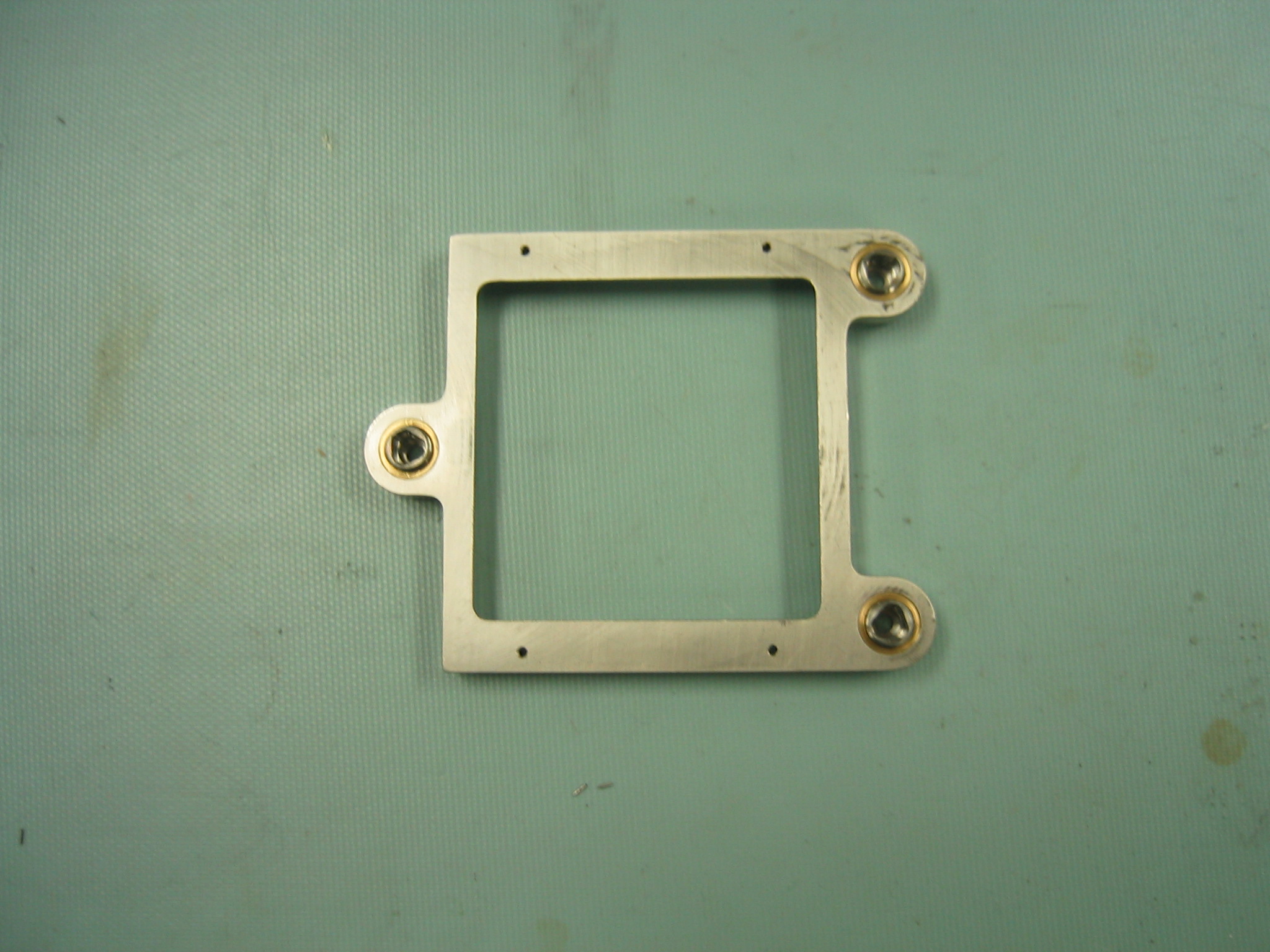 Invar mounting plate (top). |
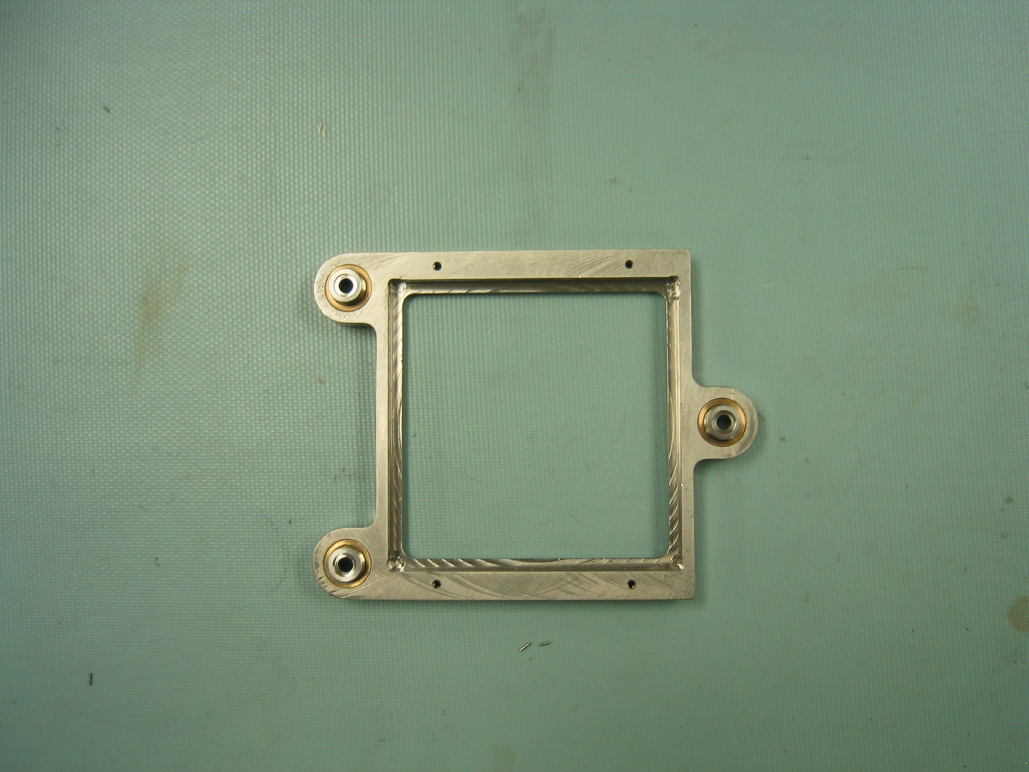 Invar mounting plate (bottom). |
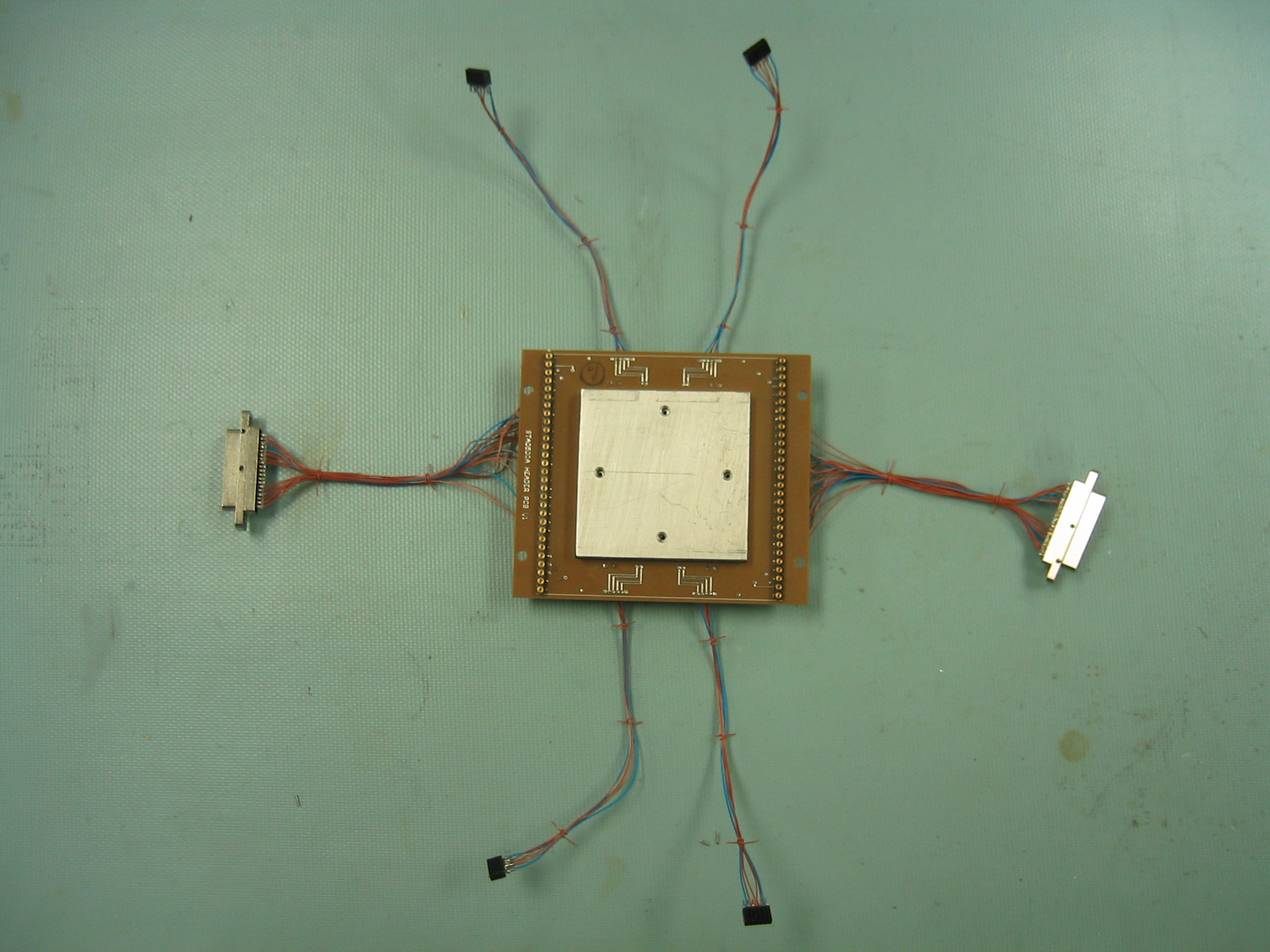 Header pcb w/o CCD (top). |
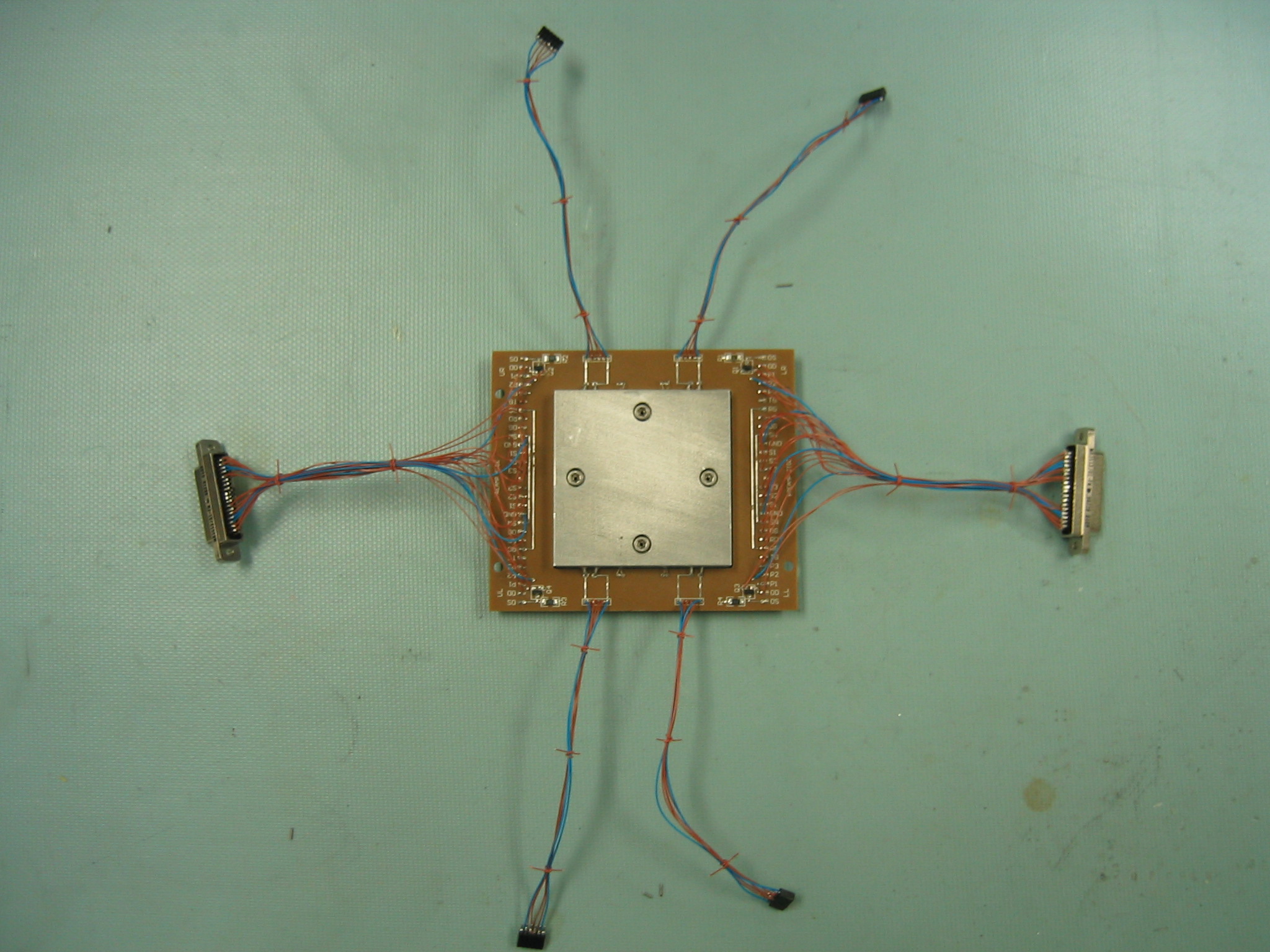 Header pcb w/o CCD (bottom). |
One side of the dewar head has a recessed sideplate (with o-ring) where we mount a preamplifier rigid-flex circuit board. The component area of the pcb is rigid, and has a flex cable which solders to the 79-pin connector. The internal board has two preamp circuits, filters for the clock and bias lines, and two temperature sensor circuits.
 Hermetic 79-pin connector |
 Rigid-flex preamp board |
The cold probe from the dewar cold surface contacts the ccd+aluminum plate assembly from underneath. Four temperature sensors and four heater resistors are fitted into the aluminum plate to stabilize the temperature.
 CCD assembly, dewar head with stand-offs. |
 Back o-ring surface. |
 Cold post and spring-loaded copper strap |
 Cryotiger compressor and cold-head. |
Test results (and known issues)
 CCD surface profiling measurement |
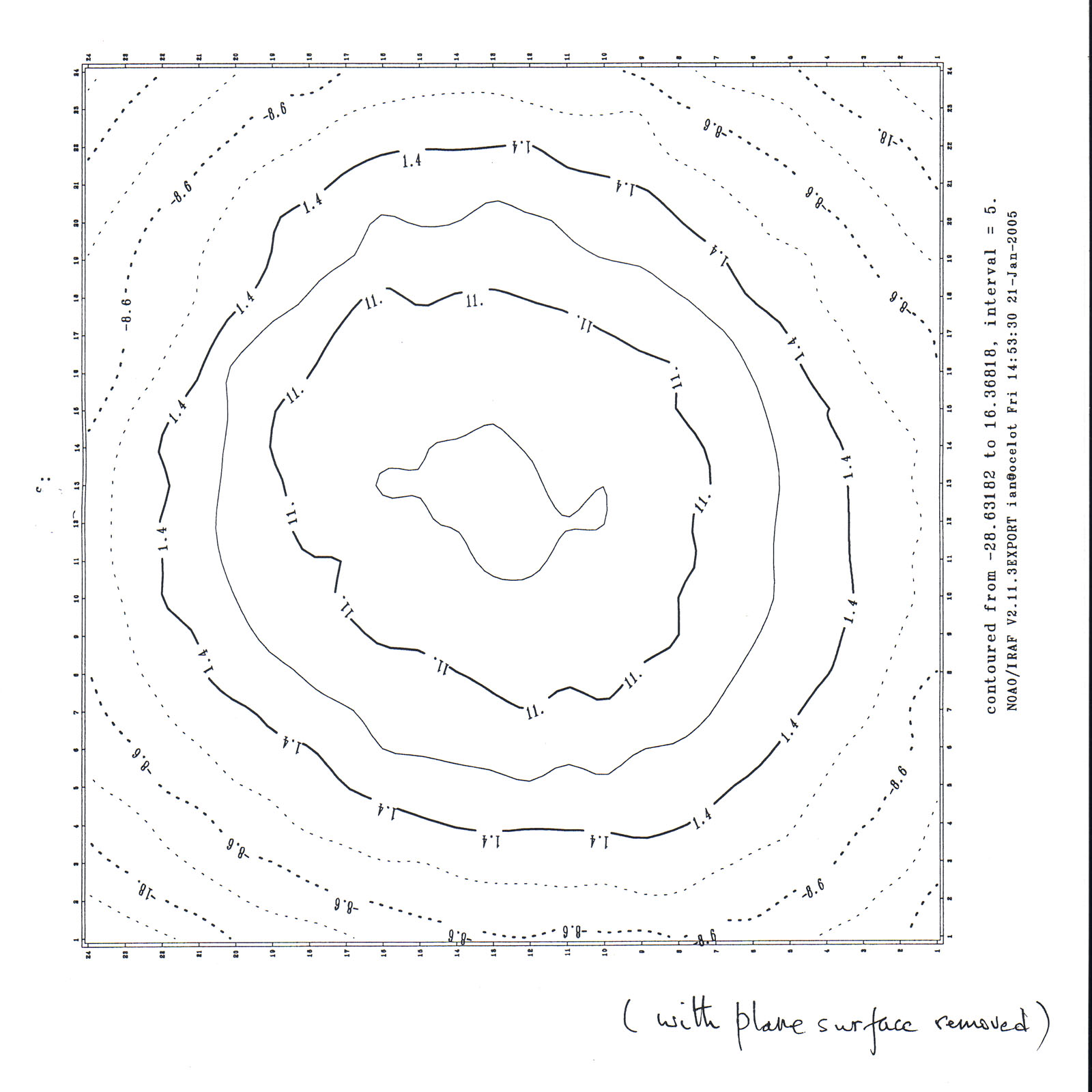 Surface flatness profile of ccd |
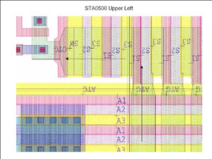 CCD gates info |
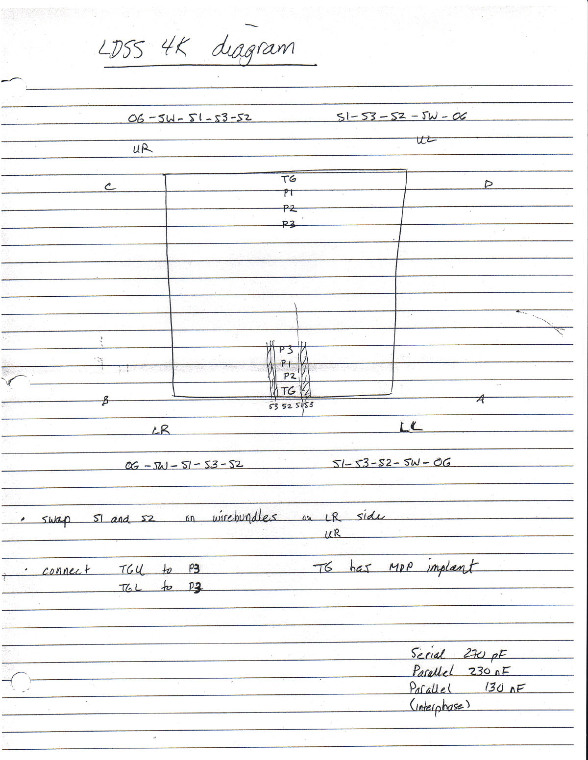 Clocking info |
Link to the CCD datasheet test results.
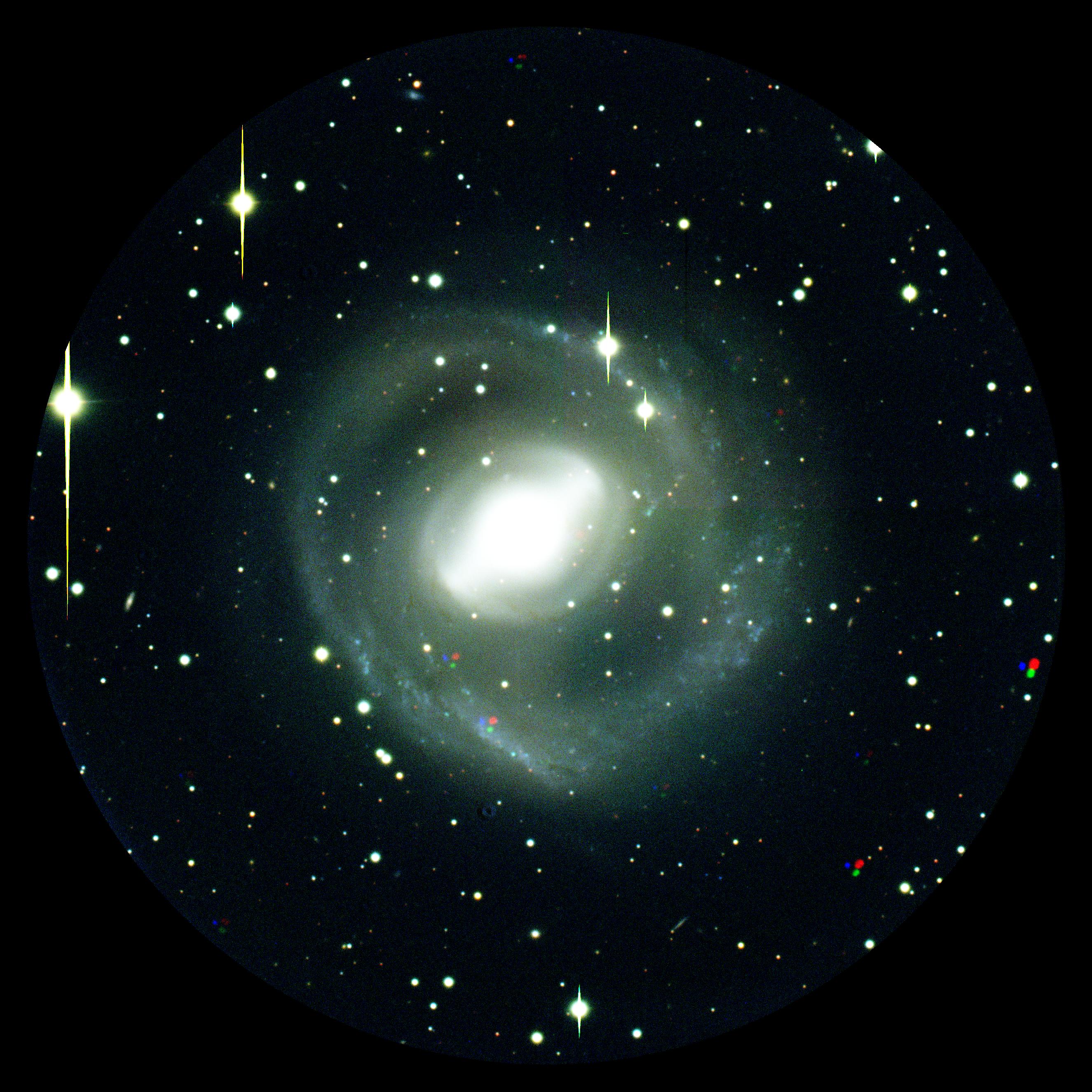 NGC2217 (courtesy D.Kelson) |
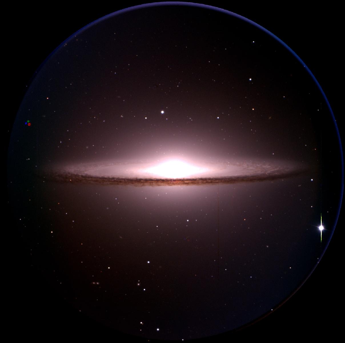 Sombrero galaxy |
[ insert jpg here ] Sample multi-slit spectra |
[ insert jpg here ] Sample nod/shuffle spectra |
| Mode | Pixel
time |
Gain | Noise |
Readout
(1×1) |
Readout
(2×2) |
| (µsec) |
(e-/DN) | (
e-
) |
(sec) |
(sec) |
|
| Fast | 9 |
0.7 | 4.5 |
80 |
24 |
| Slow | 15 |
0.75 | 3.4 |
135 |
38 |
Link
to LDSS
instrument page
Ian Thompson (ian@obs.carnegiescience.edu)