2/22/03
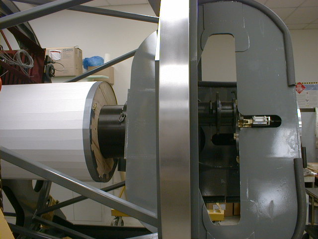
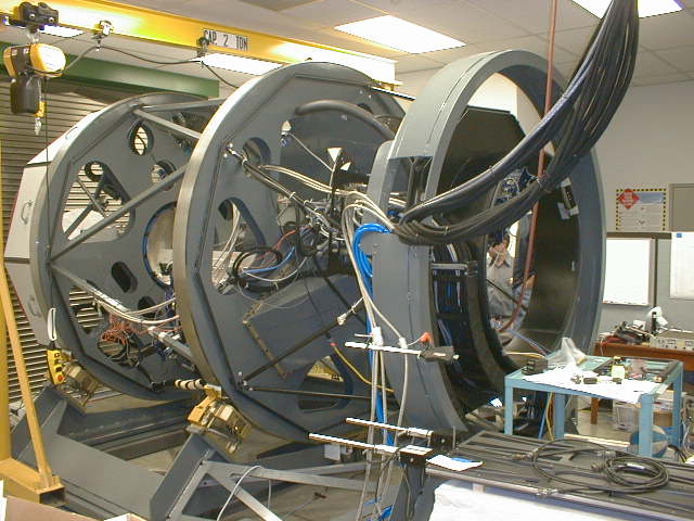
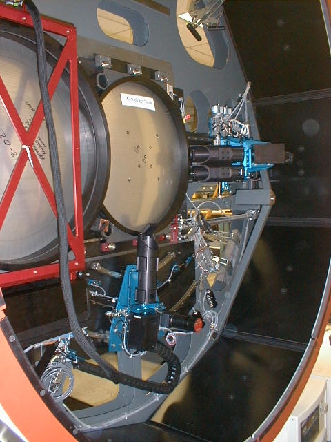
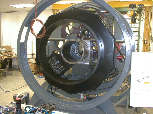
Installation of structure light baffles
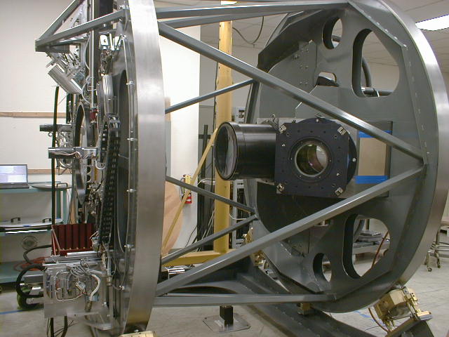
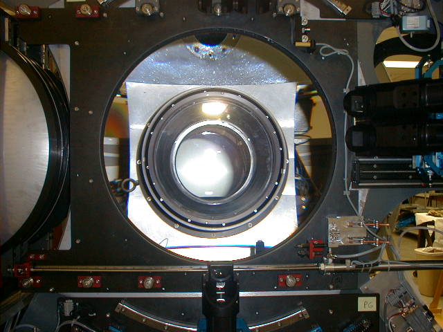
The baffle between the field lens (left, big end of cone)
and the collimator
barrel is now installed. The large black cover
at the upper left seals the area around
the mask server. The slit area is exposed to telescope
air - the rest of the instrument
is sealed at the field lens. Barbell weights near
the center of the image are ballast,
to rotationally balance the structure.
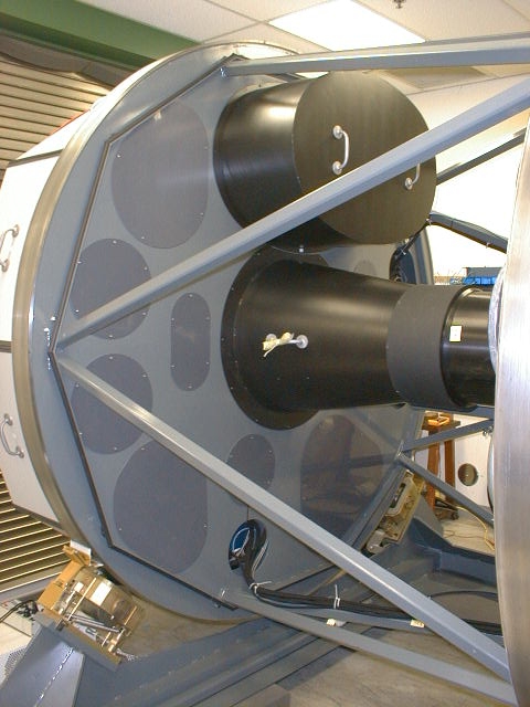
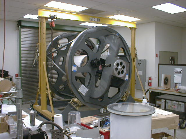
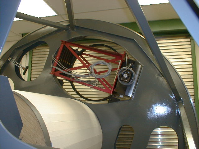
The FOSS disc is made air and light-tight by a set of
PVC plastic
covers which show up here slightly darker than the "IMACS
Grey"
structure.
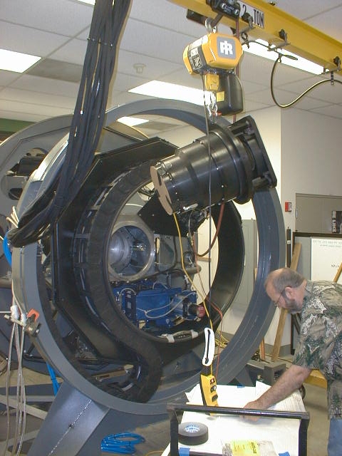
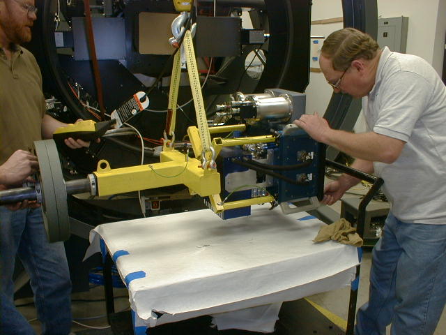
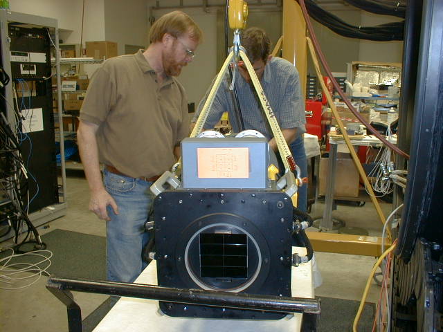
First, the short camera has to be threaded into the structure,
between the utility wrap and the mainframe.
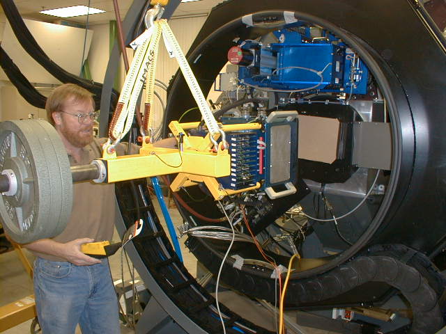
Tyson Hare installing the camera counterweight mount.
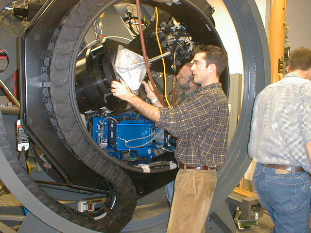
Front of the short camera on the way in.
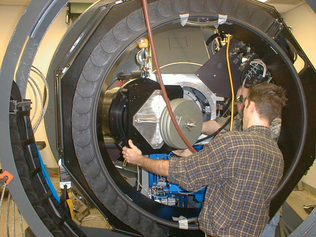
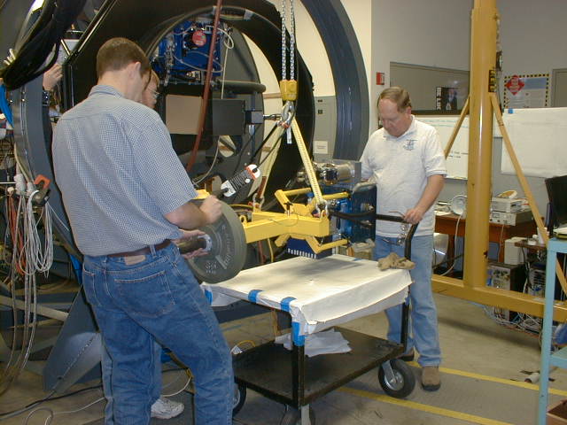
Weights installed.
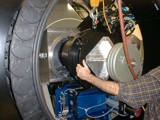
Inserting the camera in the MOSS structure.
Bigelow butts in...
Installed!
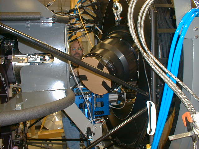
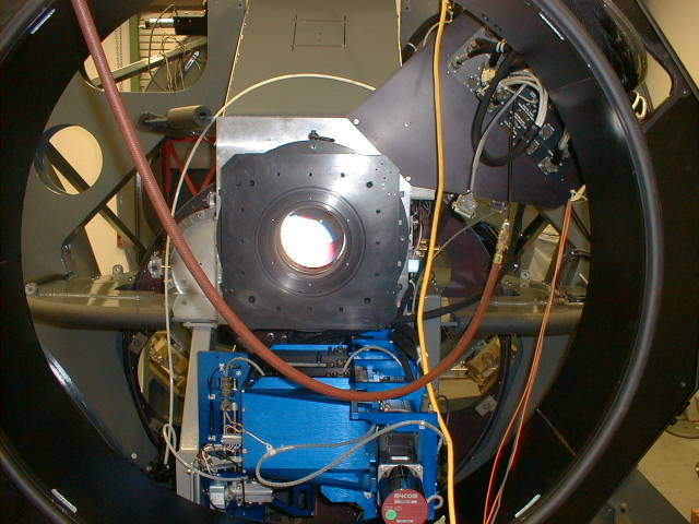
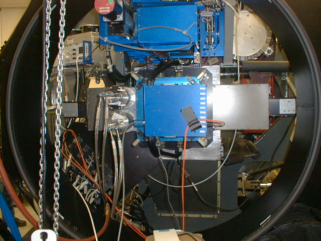
Short camera seen from the telescope focus.
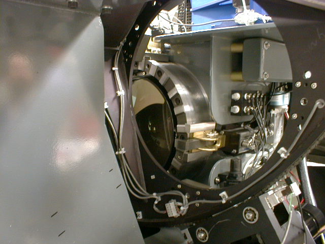
Front of short camera peeking out from behind the disperser server.
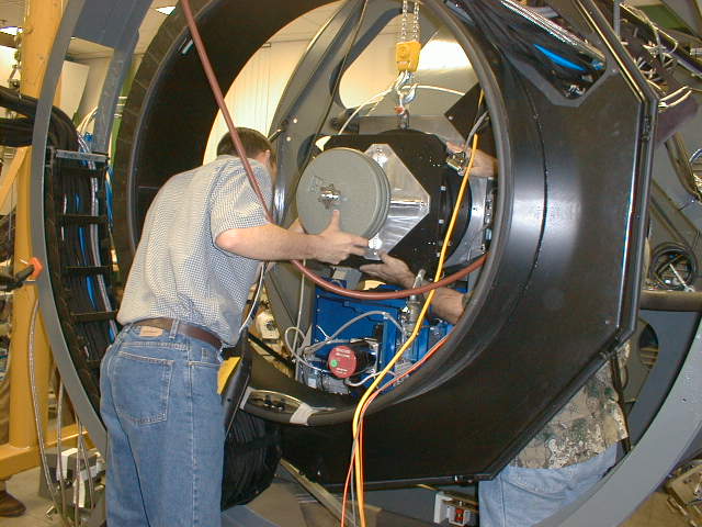
Steve Gunnels lends a hand attaching the dewar to the dewar installation too.
Bigelow can't help himself and butts in again...
Front view of the 8K array.
Ian Thompson guides $500K of silicon toward the short camera.
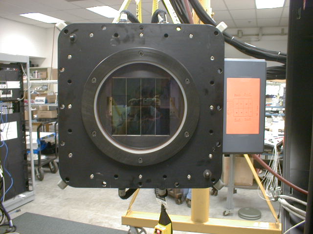
Close up of the 8K array.
Dewar installed!
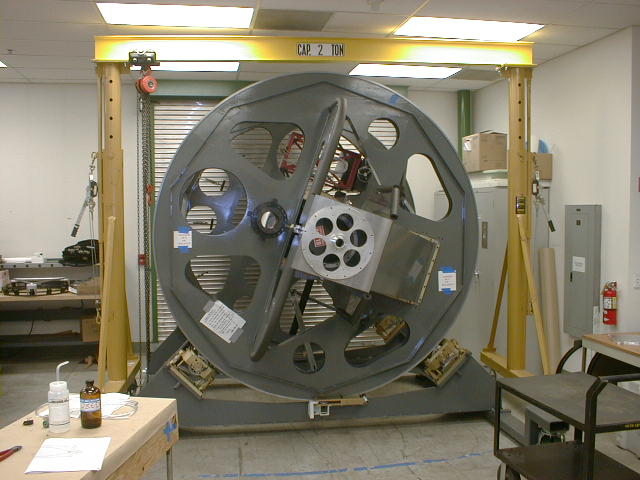
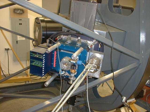
1/13/03
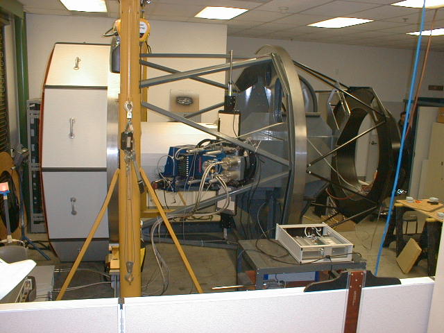
IMACS as it appeared on 1/13/03. Note that the utility
wrap (center-right) is now installed, as are
the hoses for liquid cooling and air (blue), and Cryotiger
coolant lines (silver).
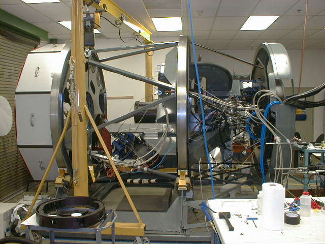
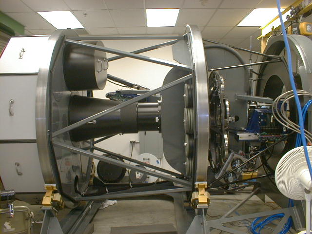
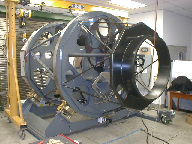
IMACS side view. Note enclosure panels mounted in
slit area (far left). The collimator,
f/4 camera, and its filter server can be seen in the
center of the instrument.
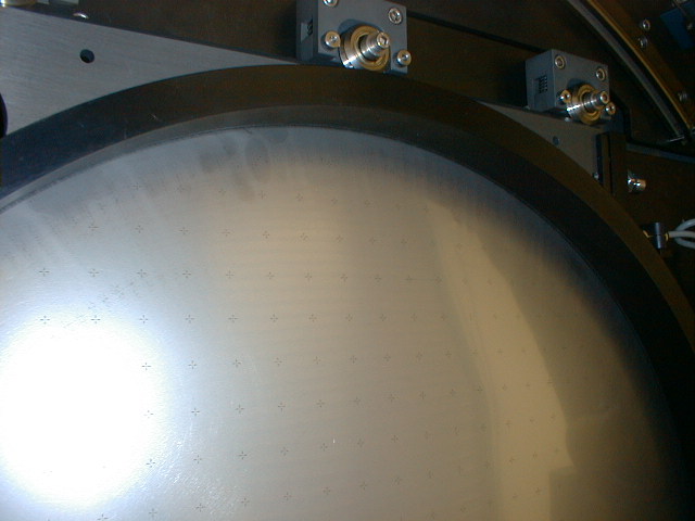
A laser-cut slit mask with about 650 cross patterns for
image testing, mounted on the mask server.
Each cross is made up of 4 small slits and a round central
hole. This mask took about 3 hours of
machine time on the laser mask cutter.
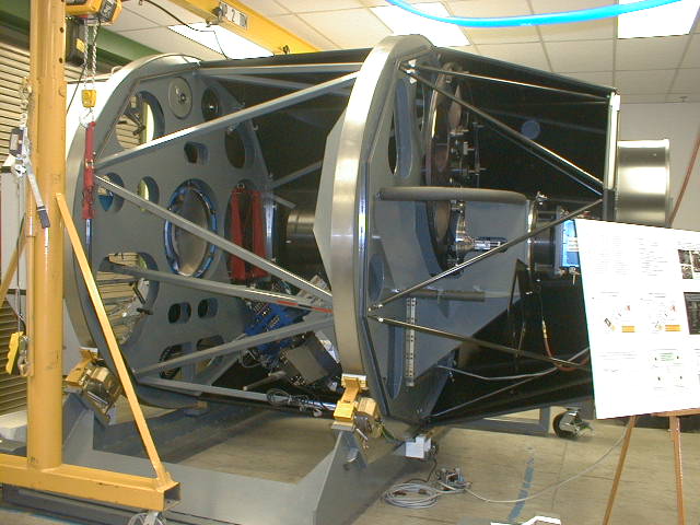
IMACS as it appeared for the OCIW open house in late October.
Note that the dewar is mounted on
the short camera barrel at the extreme right in this
image. The long camera with its shutter and
filter server can be seen in the lower middle of the
image. The slit mask server and field lens can
be seen at the far left.
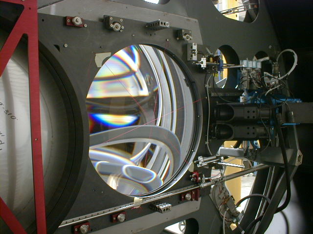
View of the slit area. A slit mask is shown in the
center of the image. Below the mask,
the principal guide camera is shown. To the left
of the mask is the mask shuttle, holding
additional (test) slit masks. At the far right,
the center field guide camera can be seen.
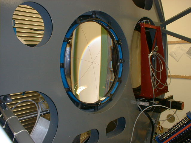
The field lens is shown with cross hairs used for alignment
of the lens and the mask transfer system.
Field lens shown with slit mask retracted. Center
field guider at right.
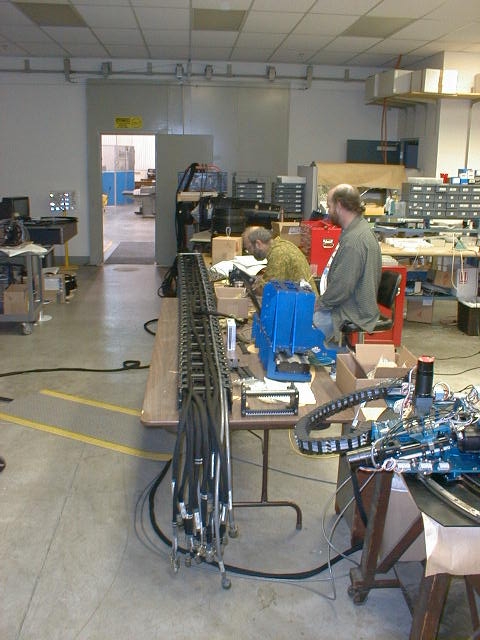
Alan Baggish and Christoph Birk with the IMACS utility
wrap. The carrier is
an IGUS chain. The flexible part of the wrap is
about 13 feet long, and the
cable length (racks to instrument bulkhead) is about
35 feet long.
The utility wrap structure. The grey ring guides
and supports the moving portion of the utility wrap.
The black inner section defines the inner radius for
the wrap, and includes a pass-through to the
instrument bulkhead (shown at the 7:00 position).
10/13/02
The dewar now has 8 detectors installed, and both cryotigers
are now
installed and operational. Black structure at right
is the rotating support
for the IGUS utility chain. The fixed IGUS support
is being re-worked at
Rettig. Note that the front enclosure panels are
finished and installed.
Work continues with installation of the middle and rear
panels.
Rear quarter view...
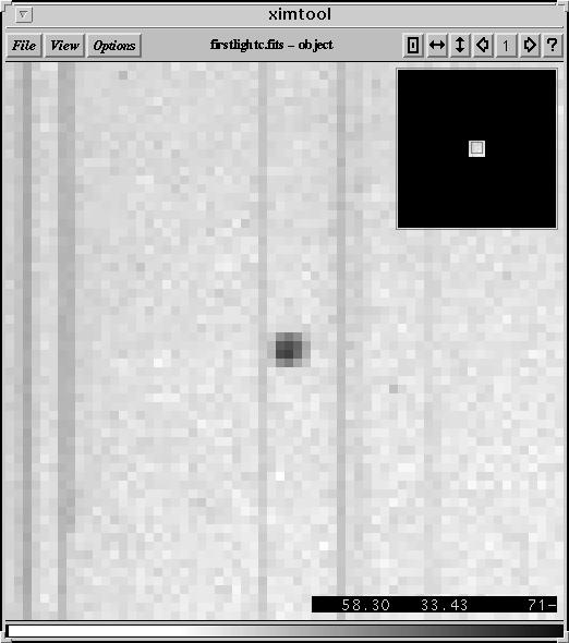
First light image taken with one of four CCDs currently
installed in the IMACS
science array. The spots are images of 0.5 arcsec
holes, on 1 arcmin centers,
on a laser-cut testing slitmask. The origin
of the shadow has not yet been
determined.
A single spot, showing most of the energy concentrated
in 3-4 0.11 arcsec pixels,
taken from the image above. Note that the holes
in the slit mask are not perfectly
round, and make a contribution to the shape of the
spot.
The dewar mounted on the back of the long camera.
Note that only one cryotiger
was installed for the first light exercise - the second
cooling head was damaged
and returned to APD for repair. The shutter
can be seen mounted in the camera
behind the dewar.
Latest flexure map. Note that the hysteresis
seen in the earlier map is almost completely
gone now. The source(s) of this flexure is still
not completely understood, although some
of it is almost certainly due to major (temporary)
imbalances in the structure. The hysteresis
seen in the previous image was probably due to loose
lens assemblies in the collimator.