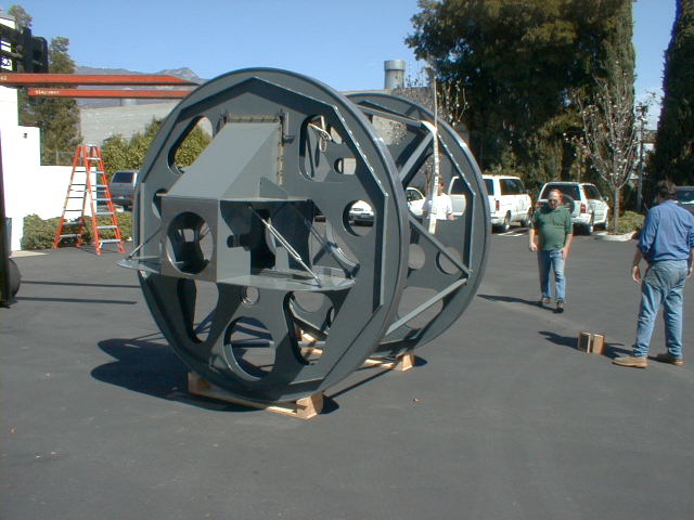
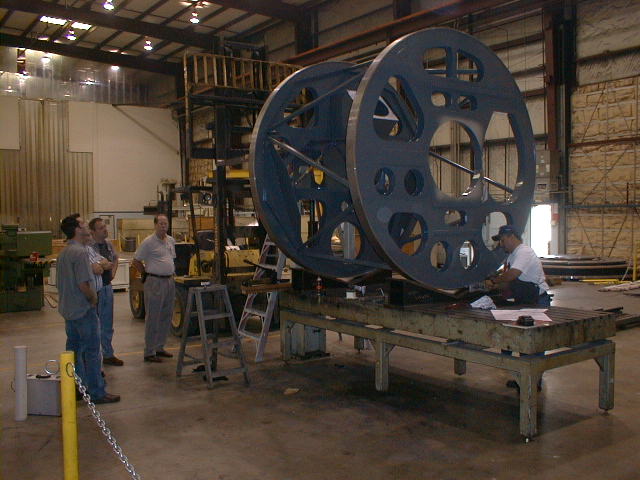
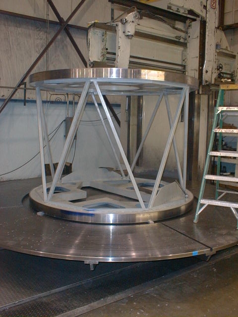
The instrument structure is composed of two large (100"
dia) disks,
which are connected to each other with a 10 element truss.
The two disks
are supported by the instrument carriage, which has rollers
that allow the
disks (and instrument) to rotate about the Nasmyth optical
axis.
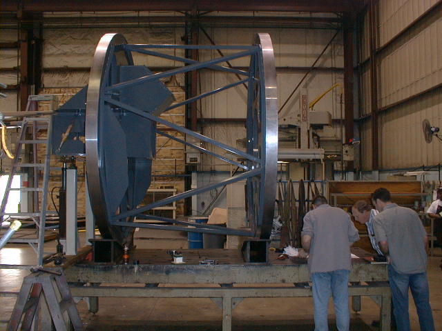
The Front Optical Support Structure disk (FOSS disk) carries
three guide cameras,
the slit-mask shuttle and transfer mechanisms, and the
field lens. The Main
Optical Support Structure (MOSS) carries the collimator,
long camera, short camera,
disperser server, and filter changers.
The total bare structure weight is about 3100 lbs.
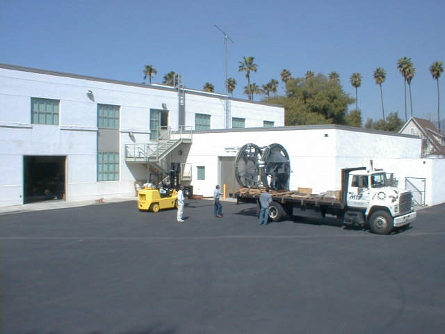
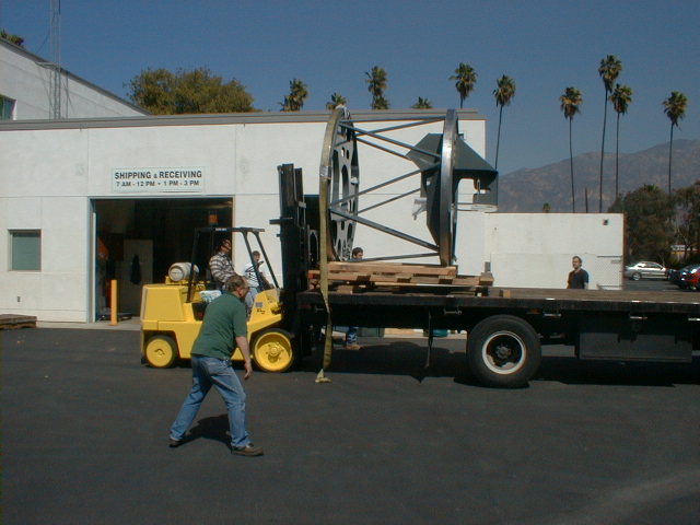
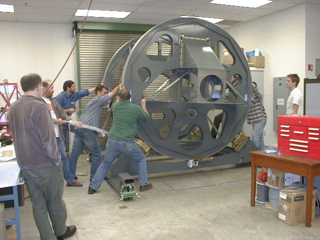
March 13, 2002 -- Delivery Day!
The M&T truck arrived at 10:30 AM on another wintery southern California morning...
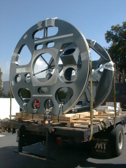
The FOSS end of the structure mounted on the back of the truck.
The scene from the top of the shop building.
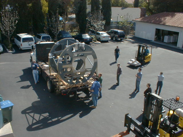
Structure on the truck, Steve Gunnels supervising the unloading...
Structure off the truck...
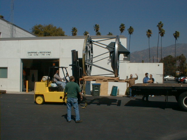
Structure on the ground...
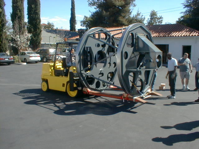
The rental forklift comes in very handy...

Now off the palette...
View from the instrument carriage...
Stucture ready for the second lift...
The first set of wood blocks didn't work quite as planned...
Up on the second lift...
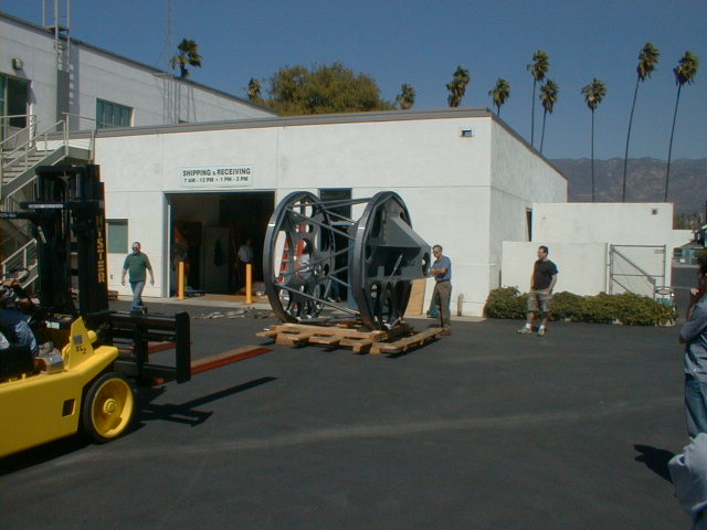
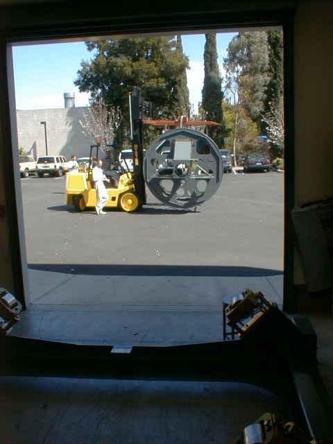
Headed into the shop - note the new, simpler blocks on the forklift forks...
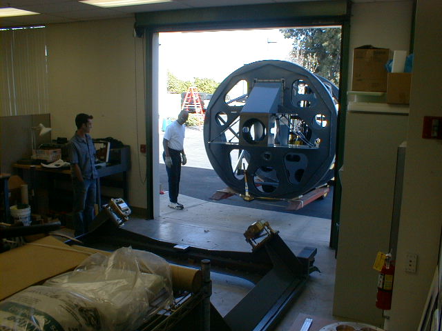
Room to spare on the way in - 120" wide door, 100" dia
structure...
Steve Gunnels supervising the installation.
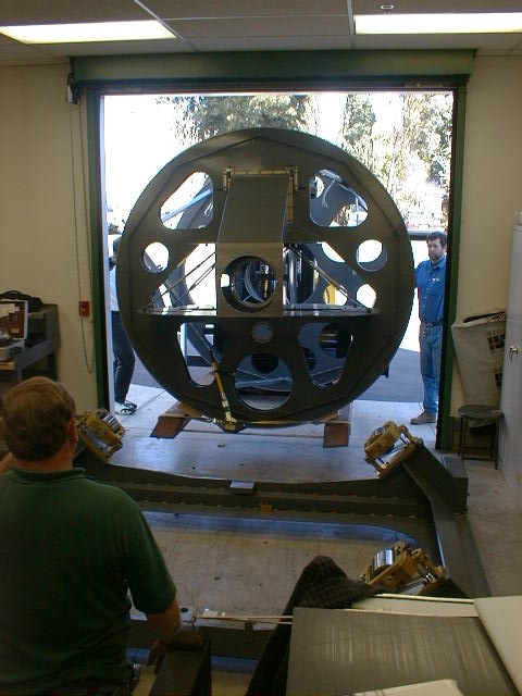
Bigelow supports the structure while Gunnels prays for the bolts to fit...
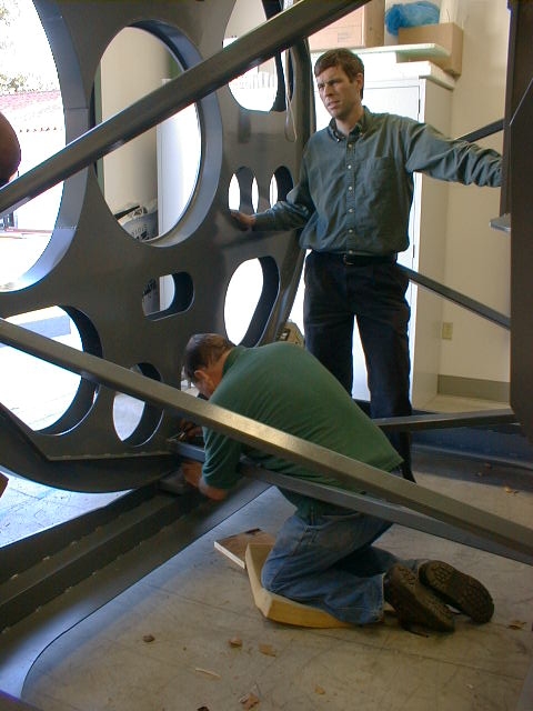
Gunnels assembles the shop drive preload.
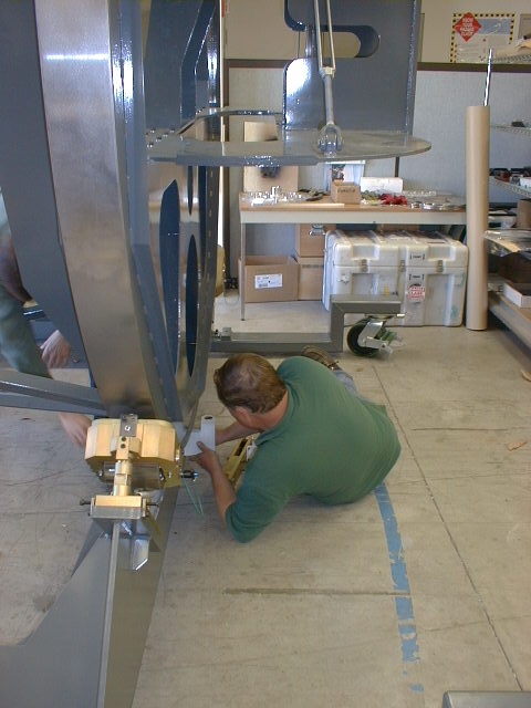
We hadn't figured it out yet, but the structure requires
about a 6 lbs. load at
the edge to rotate!
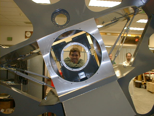
A happy PI surveys the optical axis...
The OA from the opposite direction.
The Mask transfer mechanism installed in about five minutes! Not a bad day's work...
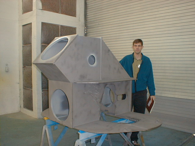
Final assembly of the MOSS and mainframe is now in progress.
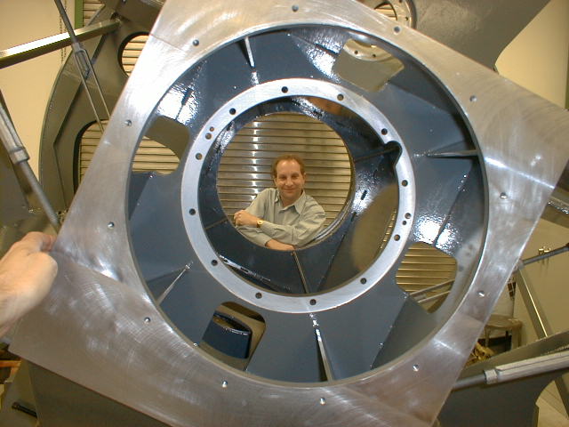
The IMACS structure
fits on a table in a small corner of the M&T facility...
The MOSS can be seen to the left, with the long camera
mounting flange pointing
up and to the right.
Tyson Hare, Steve Gunnels, and Steve Fox survey the structure.
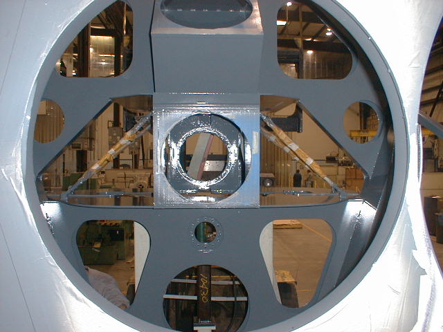
The collimator mounting flange as seen from the field lens clearance hole.
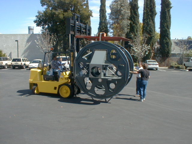
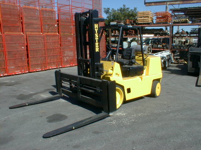
March 4, 2002
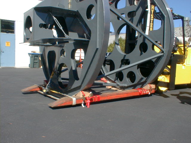
A Hyster 13,000 lb. forklift available from Industry Lift,
City of Industry, Ca.
Fork opening, and fork left/right position are both hydraulically
adjustable
($500 for one day with delivery).
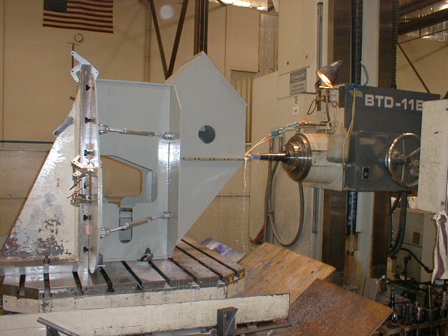
February 28, 2002
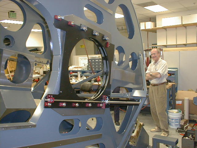
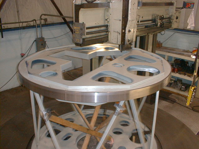
The MOSS, now prime-painted, in its final machining operation
- finishing of the bolting
strips for the interface to the mainframe. Note
the turnbuckles now in place for controlling
the MOSS/mainframe interface at the top of the upper
wing.
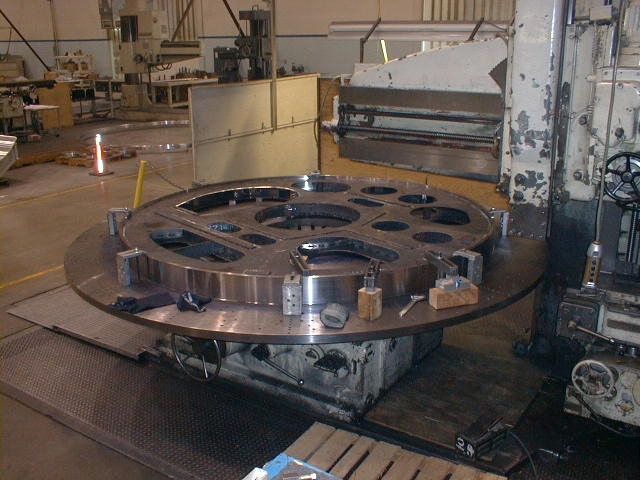
The mainframe, FOSS disc, showing final machining of guider
and SMS mounting
surfaces, and mounting holes.
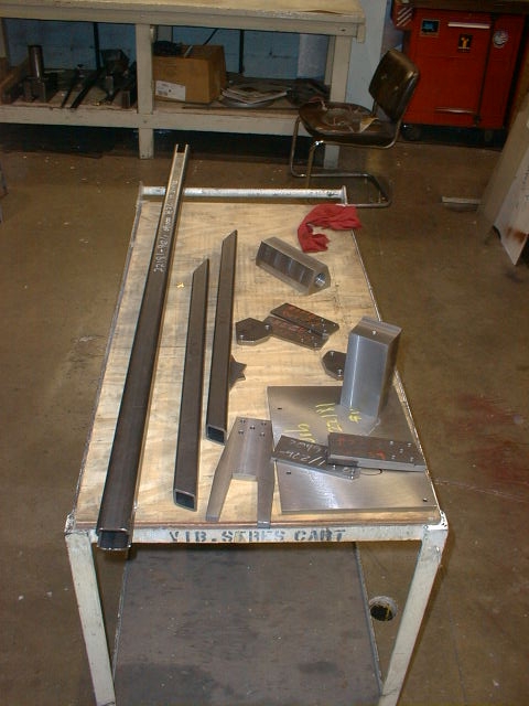
Here are the tripod parts, ready for welding and bolting to the mainframe
The mainframe on a VTL, ready for welding of the tripod
and
mounting of the MOSS box.

The only material being removed here is on the MOSS box
mounting flanges. The VTL
might not be the best machine for this job, but it was
the one available!
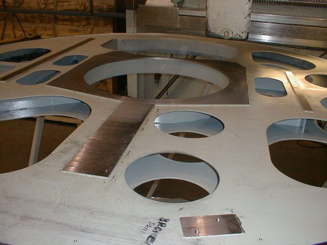
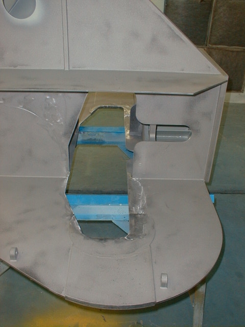
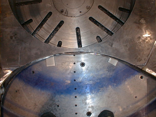
The repaired DSS cut-out in the MOSS box. Note replaced
material on
the left side of the cut-out. The MOSS was re-stress-relieved
following
these changes.
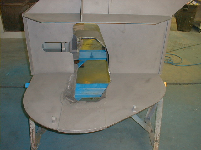
Cut-out repair from the opposite side.
Bigelow makes a rare appearance (!) at Martinez and Turek
(with the MOSS in the
paint booth)...
February 12, 2002
The mainframe welding is now complete, and shown here
following sand-blasting.
The mainframe is currently on a vertical turning lathe
for final turning operations,
and goes to a horizontal boring mill next for finishing.

Mainframe welding details. Vertical bar stock provides
the mounting surfaces for the instrument
enclosure panels.
Detail of the modified DSS cut-out. Steve, does this look right to you?
February 1, 2002
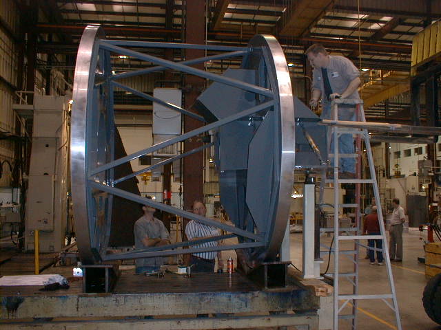
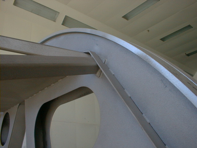
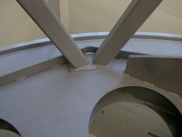
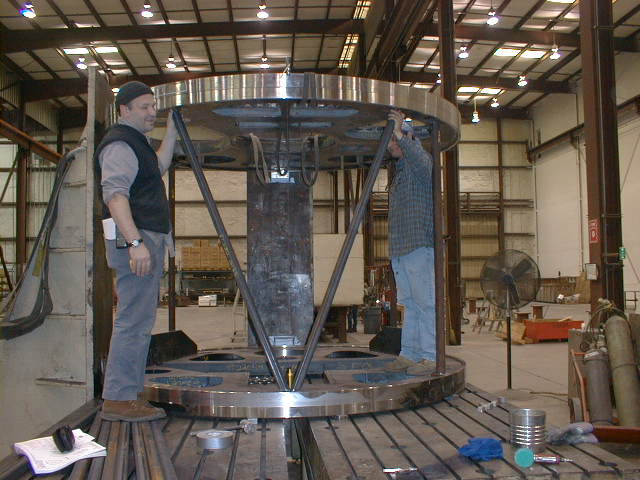
Steve Fox and Richard Vicario of M&T are fitting the
diagonal truss elements between
the FOSS (up) and MOSS (down) discs Steve
is standing on most of the truss elements!
Welding of the truss should be finished by the 6th...
These are the doubler plates for stiffening the top wing
of the MOSS. We will be
enlarging the opening in the MOSS to allow for cross-dispersing
prisms to be
mounted on top of gratings in the disperser server.

January 18, 2002
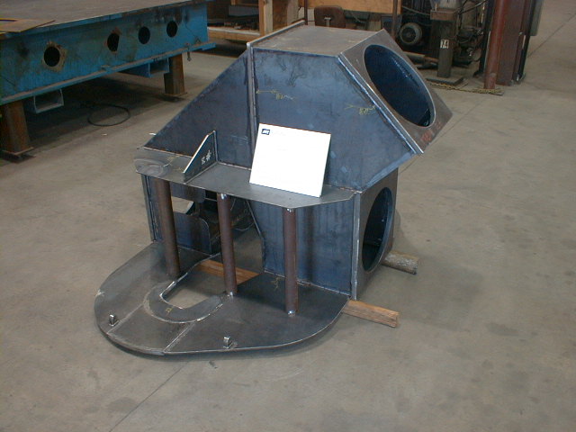
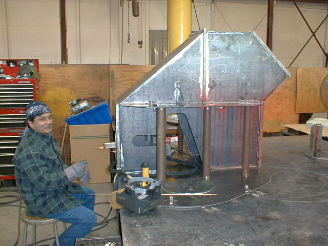
The MOSS box is not just flat plates anymore...
Richard Vicario and the MOSS.
The round tubes are temporary tooling.
Webs have been added to the stiffening rib at the bottom of the FOSS disk.
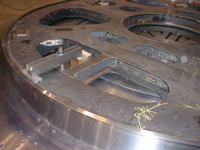
Details around the center hole and SMS hole in the FOSS
disk.
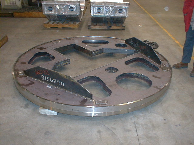
The finished MOSS disk.
January 8, 2002
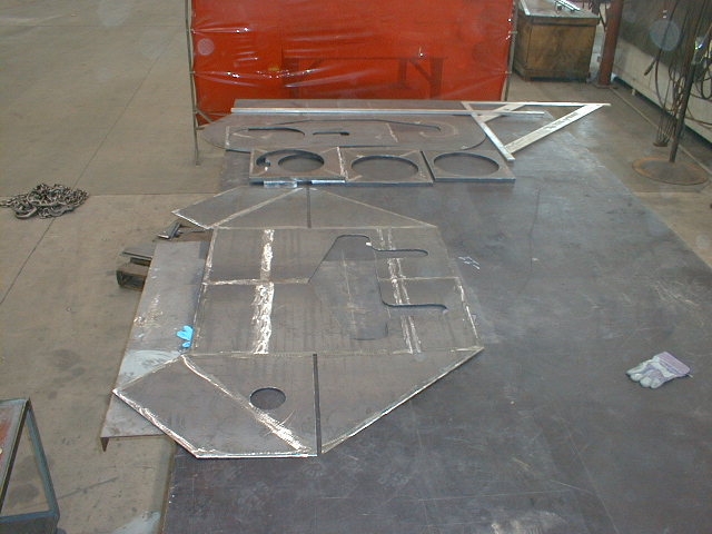
MOSS box plates ready for fit-up and welding
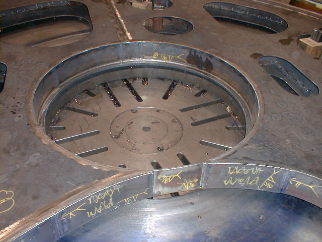
FOSS disc stiffener plate in lightening hole.
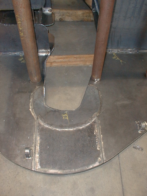
FOSS welding detail between slit-mask and center cut-outs.
FOSS disc welding partially completed
December 19, 2001
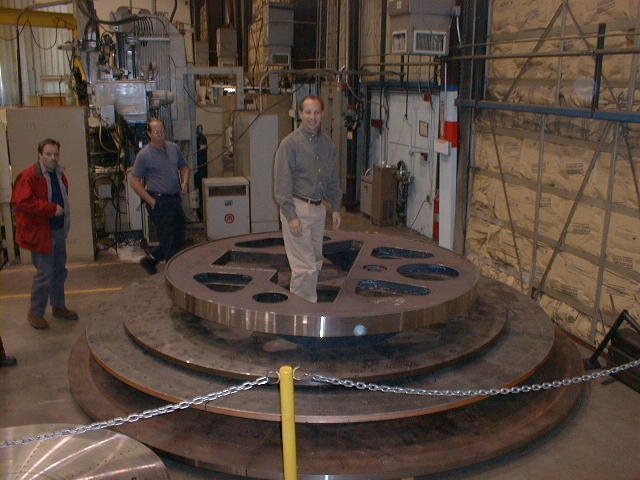
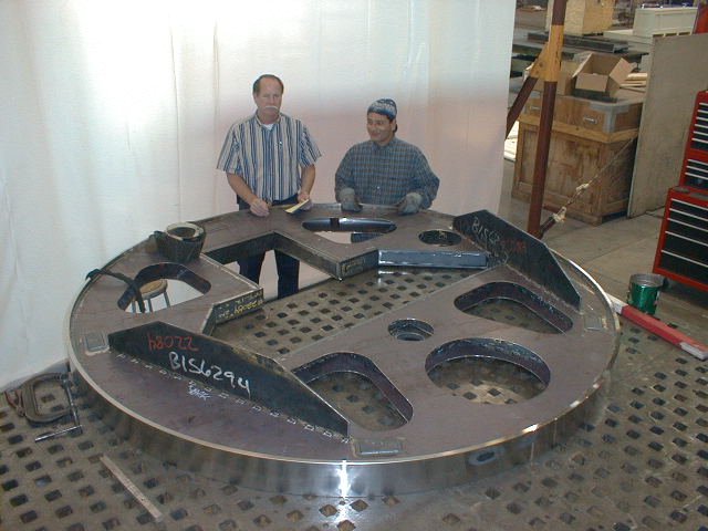
MOSS disc complete - Steve Fox, Dave Boese (M&T),
and Alan Dressler shown for scale
Plates of the FOSS disc ready for welding
December 4, 2001
Dave Boese and Richard Vicario with the MOS disk.
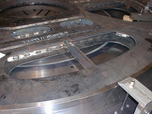
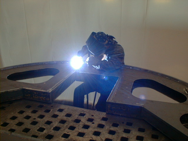
12/04/01 - Richard Vicario welding a MOS face sheet to
the rim.
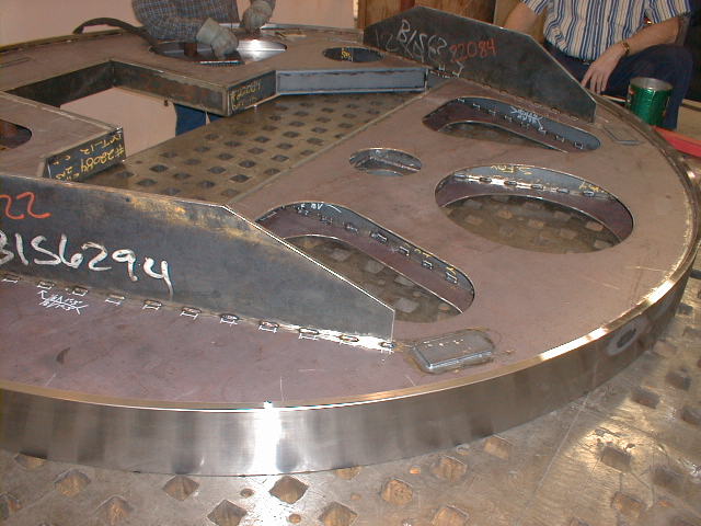
12/04/01 - MOS welding details of stiffeners and internal
webs.
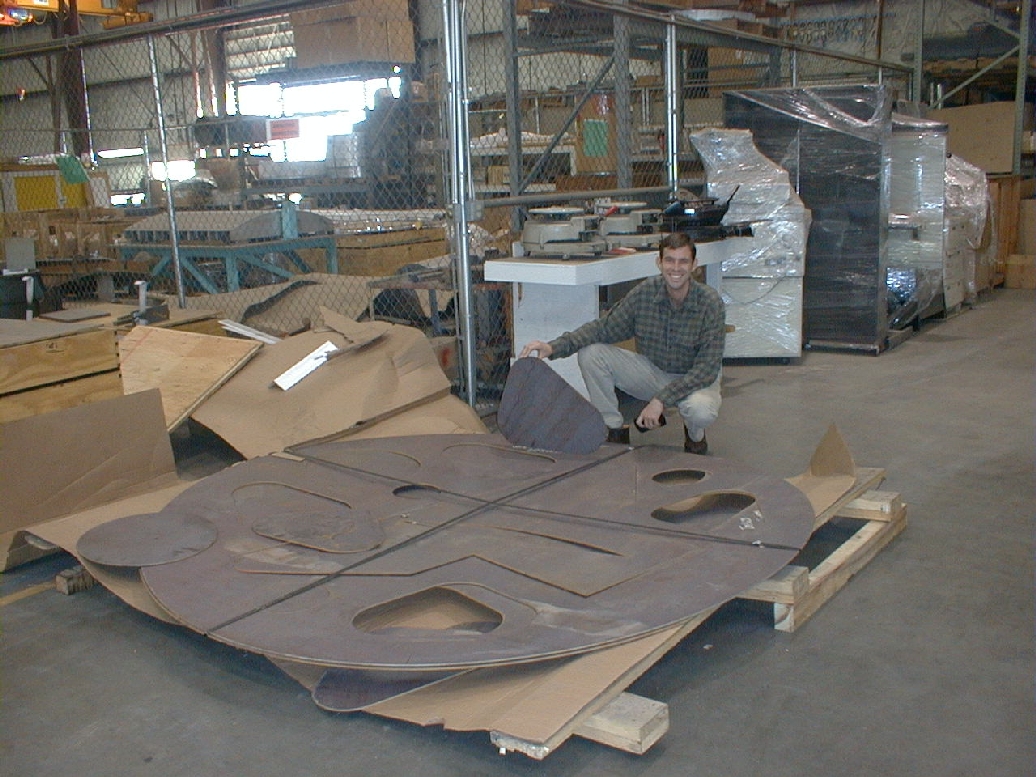
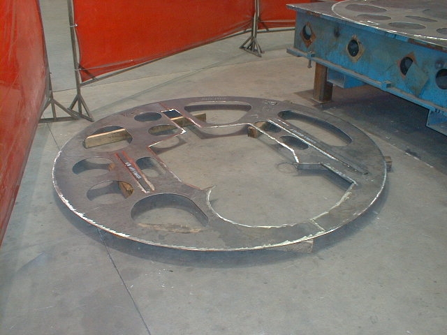
11/28/01 - This image shows the laser-cut steel disks
that will eventually form
the Main Optical Structure Disk (MOS disk), which supports
a smaller structure
(the MOS) that carries the collimator, long camera, short
camera, disperser server,
and camera filter changers.