On each side of the IMACS array, we have placed a wing chip -- these ccds are to be used to sense and correct any flexure in the spectrograph structure or optics. The flexure control ccds are 2560 × 512 pixel devices, packaged from an older Loral wafer run by GL Scientific.
Update: we've replaced the wing chips, using new devices from a wafer run by STA. The new devices have much cleaner cosmetics, CTE looks good, and the read noise is approx 3 e- in the image area and 2.1 e- in the overscan.
 Image of several spots with flexure CCD. Note the poor CTE on the right side of the device. |
 Packaged 2560×512 pixel device |
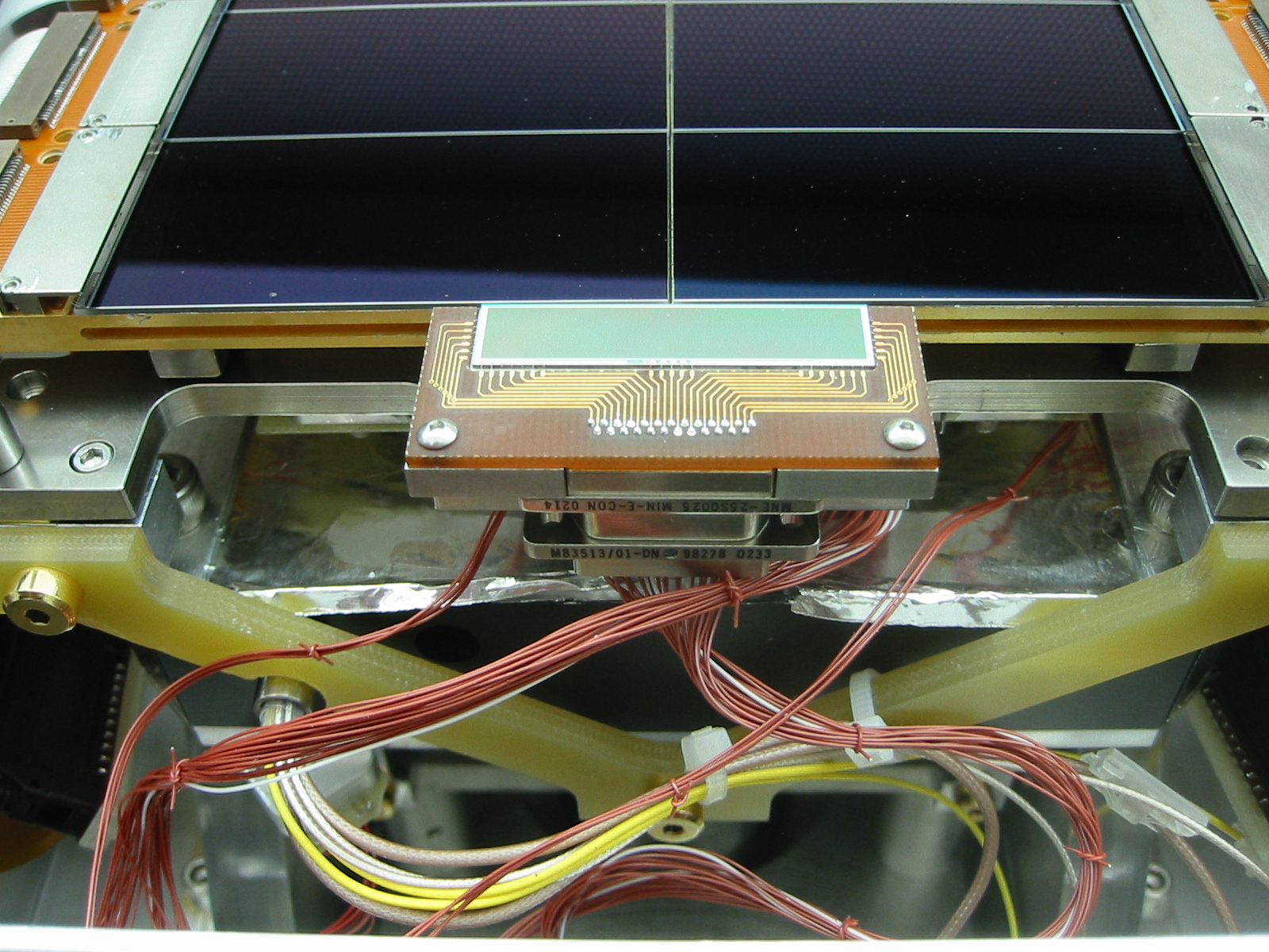 Wing chip and cable bundle |
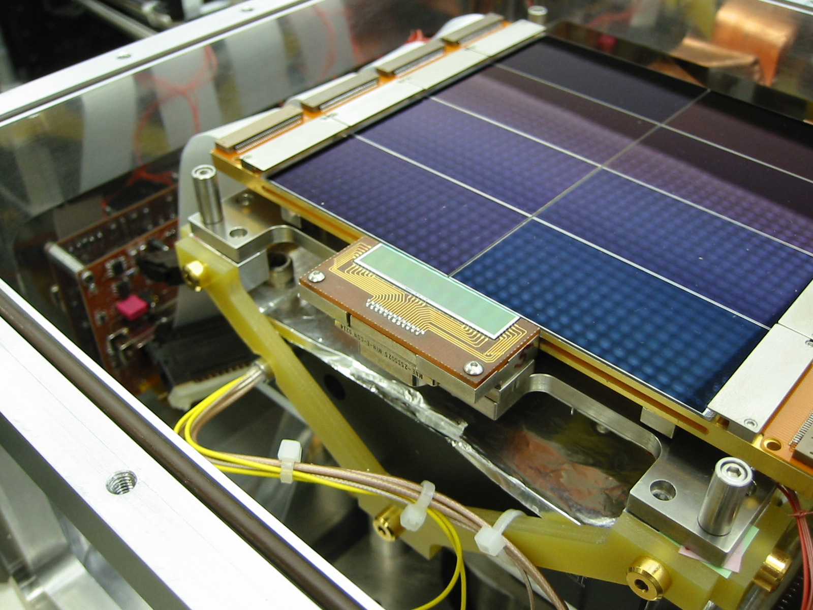 Wing chip at the edge of the IMACS array |
The ccd signals are routed to a 25-pin micro-D connector [M83513/04-DN socket] on a small circuit board which surrounds the ccd on three sides. The mating connector [M83513/01-DN plug] attaches to a constantan cable bundle which connects the chip(s) to the preamp board.
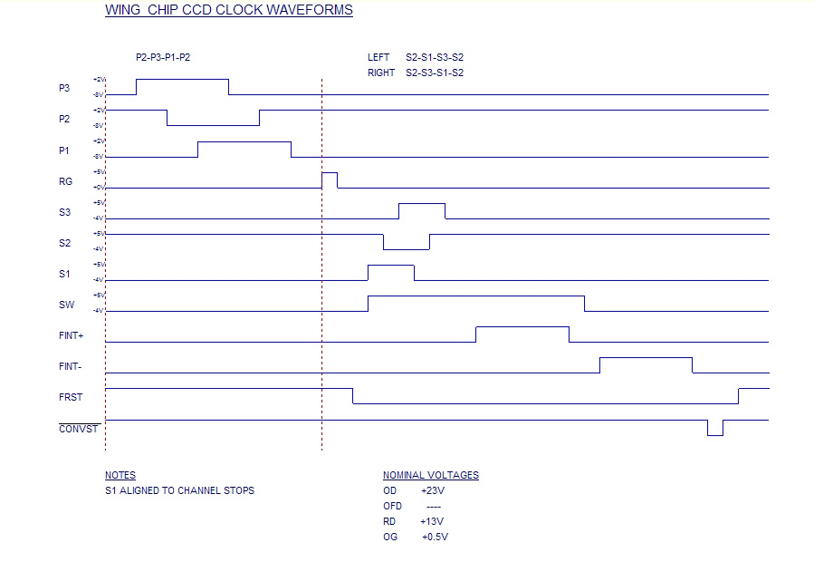
The two wing chips are clocked and read out in parallel by a two-channel version of the BASE electronics. The devices do not have a frame-transfer mask on-chip, so each exposure and readout is preceded by a fast flush.
We plan to centroid star images in direct imaging mode, or track bright sky emission lines in the spectroscopic modes. After readout and simple data reduction, the results will be used with a look-up table or closed-loop control system to minimize the spectrograph flexure.
Table
of CCD
operating
voltages
| OD | +23.0 |
V |
| RD |
+13.0 |
V |
| OG |
+0.5 |
V |
| RG |
+5.0 +0.0
|
V |
| SCLKS |
+5.0
-4.0 |
V |
| PCLKS |
+2.0 -8.0 |
V |
|
 |