External power is supplied to the guider camera from a 48 V DC power supply. On-board DC-DC converters provide ±12 volts, +5 volts, +3.3 volts and +30 volts DC. The outputs of the DC--DC converters are filtered with LC networks and ferrite beads to suppress the switching noise as much as possible.
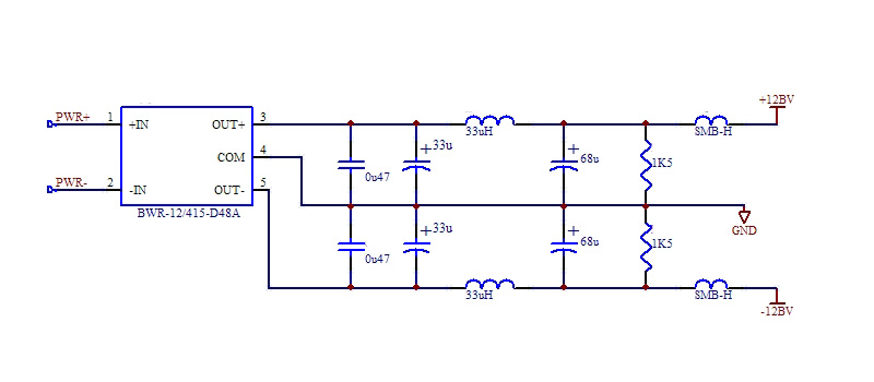
Typical power converter circuit
In addition, the high voltage +30 volt supply is linear regulated to reduce the output noise further, as this supply powers the op-amps which provide bias voltages to the CCD. (The actual voltages are generated by a DAC with 80 nV/sqrt{Hz} noise, and a precision reference).
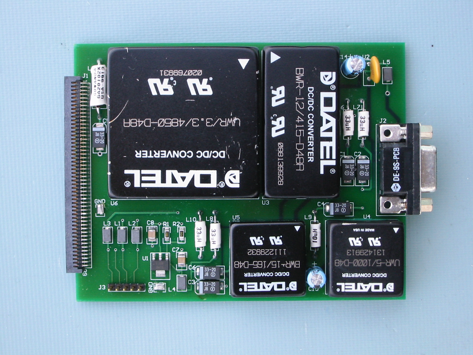
Guider camera power converter board
The DC--DC converters from DATEL/Murata
were chosen for their compact size. Equivalent linear power supplies
would
not have fit in the guider camera housing.
All analog circuits operate from the ±12volt supplies.
Where
necessary, linear regulators provide ±5 volts (for example, as a
quiet supply for ADC and DAC components) or ±10 volts (a reduced
voltage for the analog switches).
The digital circuits operate in a mixed 5V/3.3V environment. Power is provided at +5V, and is regulated to +3.3V where necessary.
A separate single output +3.3 volt DC-DC converter provides sufficient current (3 amps) to drive the two-stage thermoelectric cooler. The thermoelectric cooler current is handled by a power MOSFET in a voltage to current feedback loop, allowing the TE current to be set by a programmable D/A converter output.
Link to power consumption spreadsheet
Greg Burley (burley@obs.carnegiescience.edu)
Ian Thompson (ian@obs.carnegiescience.edu)