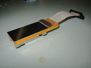
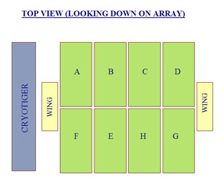
The IMACS array uses the SITe ST-002A CCD detectors thinned and back-side illuminated, with 2048 × 4096 15µm pixels. The cosmetic requirements lead to the acquisition of devices falling in between SITe grade "0" and grade "2" quality. The devices are mounted on Invar packages. Electrical connection to the devices is made via a 3-inch long ribbon cable assembly.
The BASE camera electronics will support various detector choices without modification. A custom wire bundle may be required to connect the CCD to the preamp board connector(s).
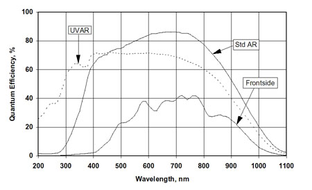
Typical QE curve for SITe ST-002A (at room temperature)
IMACS
CCD Properties (from SITe test reports)
| CCD # |
Grade |
Flatness |
Read
noise |
Gain |
Full well |
Dark
current |
ΔCTE |
| (µm
P-V) |
(e-) |
(µV/e-) |
(e-) |
(pA/cm2) |
(ppm) |
||
| 98421FABR09-01 IMACS F |
2 |
13 |
6.2 5.5 |
1.6 1.4 |
66000 |
7.0 |
2 |
| 98421FABR05-02 IMACS E |
2 |
12 |
6.0 4.9 |
1.7 1.7 |
75000 |
8.0 |
2 |
| 98372FABR06-02 MIKE_RED |
2 |
13 |
6.0 4.5 |
1.3 1.5 |
67000 |
7.0 |
2 |
| 98392FABR10-01 MIKE_BLUE |
2 |
9 |
4.8 5.4 |
1.6 1.4 |
64000 |
6.0 |
2 |
| 98392FABR08-02 IMACS A |
0 |
12 |
5.5 5.3 |
1.6 1.6 |
81000 |
10.0 |
3 |
| 98421FABR03-02 IMACS B |
2 |
13 |
5.1 4.7 |
1.4 1.5 |
69000 |
18 |
2 |
| 7273FBR12-02 IMACS C |
0 |
12 |
5.6 6.0 |
1.6 1.8 |
91000 |
15 |
2 |
| 98392FABR10-02 SPARE |
0 |
10 |
5.5 5.6 |
1.6 1.6 |
67000 |
6.0 |
2 |
| 7223FBR07-01 IMACS D |
2 |
12 |
4.4 5.1 |
1.5 1.3 |
68000 |
23 |
1 |
| 7323FBR02-02 IMACS H |
2 |
9 |
5.8 4.7 |
1.7 1.8 |
77000 |
55 |
2 |
| 7102FBR07-01 IMACS G |
2 |
10 |
5.0 5.1 |
1.8 1.7 |
66 |
1 |
IMACS CCD clock and bias voltages
| A |
B |
C |
D |
E |
F |
G |
H |
|
| P3+ |
+5.2 |
+5.6 |
+6.7 | +7.0 | +5.3 | +7.0 | +6.1 | +4.9 |
| P3- |
-7.5 |
-7.5 | -7.0 | -7.0 | -7.0 | -7.0 | -6.1 | -7.3 |
| P2+ |
+2.5 |
+2.0 | +2.5 | +2.0 | +2.5 | +2.0 | +0.5 | +2.0 |
| P2- |
-9.0 |
-10.0 | -9.0 | -9.5 | -9.0 | -10.0 | -10.0 | -9.5 |
| P1+ |
+2.5 | +2.5 | +2.5 | +2.0 | +2.5 | +2.0 | +0.5 | +2.0 |
| P1- |
-9.0 | -10.0 | -9.0 | -9.5 | -9.0 | -10.0 | -10.0 | -9.5 |
| TG+ |
0.0 |
0.0 | 0.0 | 0.0 | 0.0 | 0.0 | 0.0 | 0.0 |
| TG- |
0.0 | 0.0 | 0.0 | 0.0 | 0.0 | 0.0 | 0.0 | 0.0 |
| SCLK+ |
+5.0 |
+5.0 | +5.0 | +5.0 | +5.0 | +5.0 | +5.5 | +5.5 |
| SCLK- |
-6.5 |
-7.0 | -7.0 | -7.0 | -6.8 | -6.5 | -6.2 | -7.0 |
| SW+ |
+5.0 | +5.0 | +5.0 | +5.0 | +5.0 | +5.0 | +5.0 | +5.0 |
| SW- |
-6.0 | -6.0 | -5.0 | -5.0 | -6.0 | -6.0 | -5.0 | -6.0 |
| RG+ |
+12.0 |
+12.0 | +12.0 | +12.0 | +12.0 | +12.0 | +12.0 | +12.0 |
| RG- |
-0.0 |
-0.0 | -0.0 | -0.0 | -0.0 | -0.0 | -0.0 | -0.0 |
| IPC+ |
+5.0 |
+5.0 | +5.0 | +5.0 | +5.0 | +5.0 | +5.0 | +5.0 |
| IPC- |
-0.0 |
-0.0 | -0.0 | -0.0 | -0.0 | -0.0 | -0.0 | -0.0 |
| OD |
+25.0 |
+25.0 | +25.0 | +25.0 | +25.0 | +25.0 | +25.0 | +25.0 |
| OFD |
+20.0 |
+20.0 | +20.0 | +15.0 | +20.0 | +20.0 | +15.0 | +20.0 |
| RD |
+13.5 |
+13.5 | +13.5 | +15.0 | +13.5 | +13.5 | +15.0 | +13.5 |
| OG |
-4.0 |
-4.0 | -3.5 | -4.0 | -4.0 | -4.0 | -4.0 | -4.0 |
| ADJ |
-1.60 |
-1.48 | -1.28 | -1.26 | -1.53 | -1.40 | -1.64 | -1.40 |
| OFF |
-0.64 |
-0.51 | -0.48 | -0.55 | -0.66 | -0.64 | -0.76 | -0.60 |
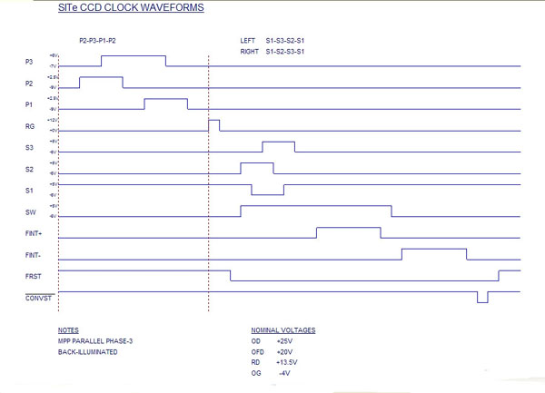
SITe ST-002A Timing diagram
Each parallel clock phase is 1200 µs, with an overlap of 400 µs. Each serial clock phase is 225 ns, with an overlap of 75 ns.
IMACS
array readout time vs noise values (at -110 C)
| Readout
time (seconds) |
Noise (electrons) |
Gain (e-/DN) |
| 44 |
7.9 |
3.3 |
| 69 |
5.9 |
1.8 |
| 104 |
4.5 |
0.8 |
| 129 |
4.0 |
0.4 |
The table shows a matrix of readout noise for a single detector as a function of pixel time and gain. All eight IMACS ccds are read out in parallel, so the mosaic readout time is the same as that for one chip.


