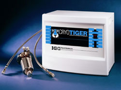
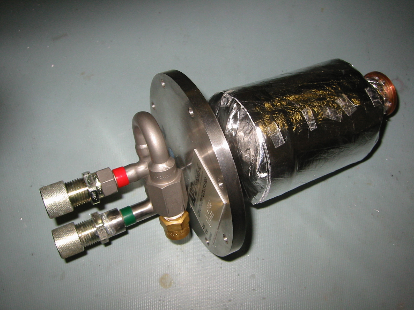
To cool the detector array, two IGC Polycold Cryotiger closed-cycle coolers are mounted on the side of the dewar. The two cold heads are operated by their own compressors, which can be mounted up to 45 meters away from the cold ends. The cold heads are mylar-wrapped and fit into an aluminium sleeve that is sealed with an o-ring at each end. We have added a mechanical strain-relief to the cooling line fittings. Not shown in the photos are the armoured supply and return hoses which connect the cold head to the commpressor.
 |
 |
 |
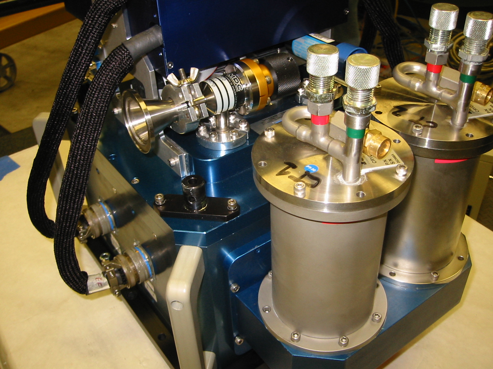 |
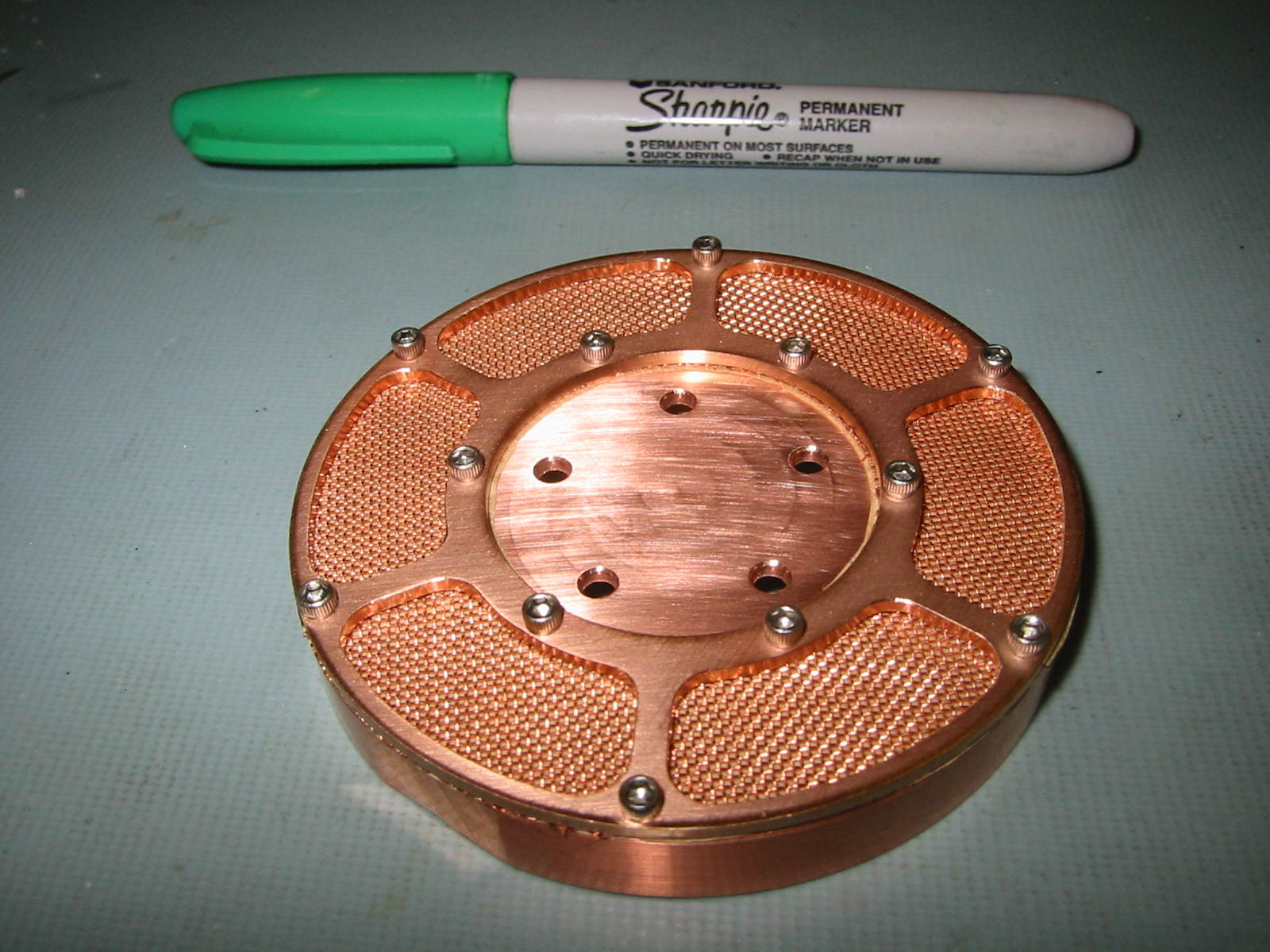
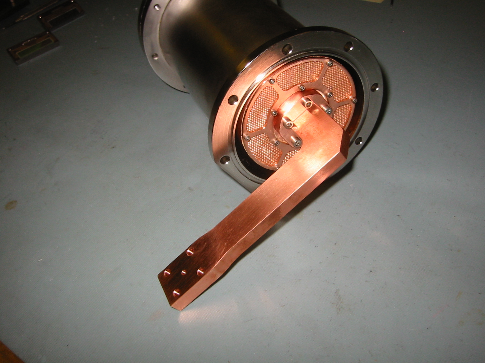
The dewar uses activated charcoal as a getter. The getter material is contained in a copper can, with a wire mesh screen (as shown). The can is in the form of an annular ring which bolts onto the cryotiger cold surface (drawing available here).. Each of the two cold heads has a getter can which holds about xxx grams of material.
 |
 |
 |
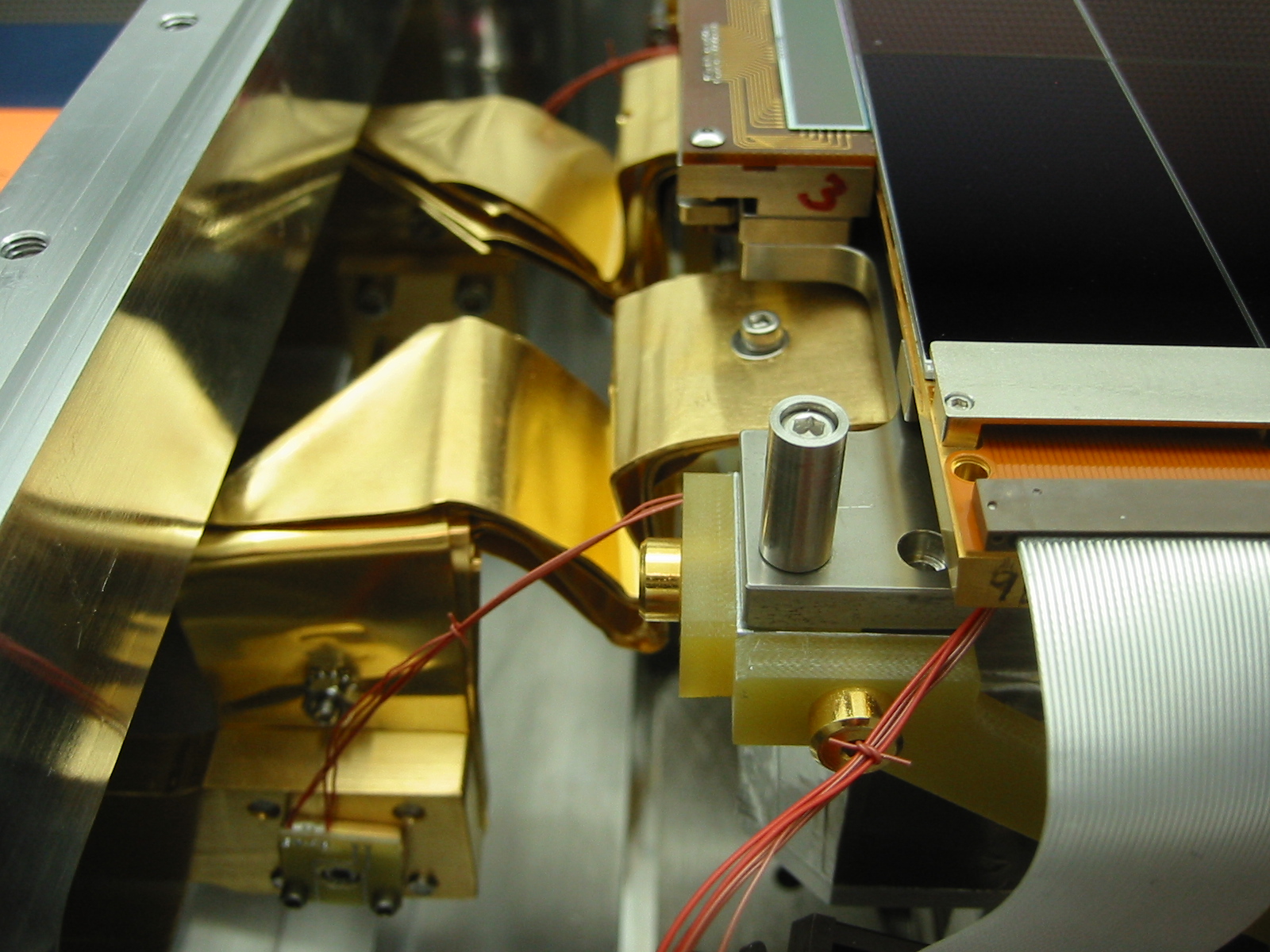 |
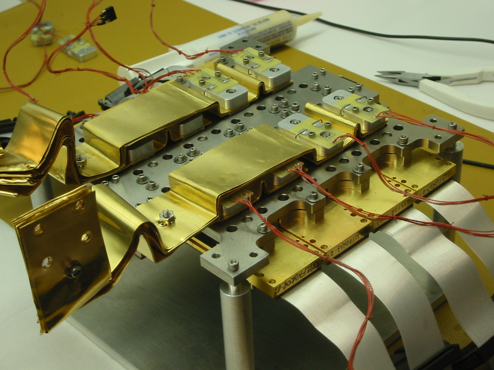
Flat copper straps in multiple thin layers connect the CCDs to the cold surfaces of the cryotigers. Each copper strap is 1.25 inches wide, and 0.010 inch thick. The straps are gold-plated to reduce thermal emissivity. The straps have two folds in them to allow for thermal expansion/contraction without putting stress on the ccds or the piezo-stage holding the platten.
Each row of the four ccds is connected to a cryotiger. The copper straps connect the ccds in pairs, and are connected to a copper bar from the cryotiger cold head. For each row, the two chips nearest the cryotigers are connected with three straps, while the two chips farthest are connected by seven straps. [Since the cryotiger cold surface is at about -150 °C, rather than liquid nitrogen -200 °C, the copper cold straps are more substantial for the cryotiger to achieve the same ccd operating temperature of -110 °C].
One disadvantage of connecting the ccds in paris is that the chip nearest the cryotiger is always slightly colder than the chip furthest away (by about 3 °C). The ccds have individual temperature sensors and heater resistors. We control the temperature of each pair in a PID loop that senses the temperature of the warmer chip, but uses both heater resistors to stabilize the temperature (at a nominal -110 °C).
Our original arrangement had the two cryotiger cold ends connected together by a copper bar. A set of straps then connected from the cold bar to all eight ccds. Later, we switched to the current arrangement where each cryotiger connects directly to the thermal load, without the shorting bar between them. This appears to be a more efficient arrangement and gives a colder temperature for the ccds, but we also use wider straps which would account for some of the result.
The cryotigers use PT-30 gas. With no load, the cold head gets to about -160 °C. With the fully loaded mosaic, the two coolers can bring the chips to –100°C in approximately 5 hours. The cold head temperatures stabilize at -150 °C, while the ccd temperatures stabilize between -110 °C and -120 °C for the eight detectors.
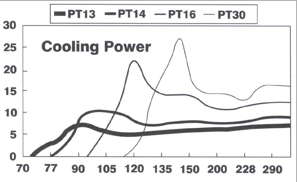
[ insert cooling curve ]
Normal compressor pressures are 218 and 212 psi when switched off (see table). One operational issue is that the cold head cannot be disconnected from the compressor until the compressor is switched off and the pressure has returned to its nominal value (or the head warms to room temperature). Our tests indicate that equalizing the pressure takes about two hours. So, switching the dewar between the IMACS f/2 and f/4 camera positions requires careful planning.
IMACS
dual cryotiger pressure measurements
| Time | Cryotiger 1 Pressure (psi) |
Cryotiger 2 Pressure (psi) |
Dewar pressure ( x 10-3 mbar) |
|
| 10:55 | 5 | 5 | 1.7 | |
| 10:57 | 180 | 174 | |
cryotigers switched off |
| 11:00 | 185 | 176 | 2.0 | |
| 11:05 | 189 | 181 | 2.4 | |
| 11:10 | 192 | 182 | 3.3 | |
| 11:15 | 193 | 184 | 1.3 | vacuum pump on |
| 11:20 | 194 | 186 | 0.5 | |
| 11:25 | 194 | 186 | 0.2 | |
| 11:30 | 195 | 186 | 0.2 | |
| 11:45 | 197 | 188 | 0.1 | |
| 12:30 | 205 | 200 | 0.6 | |
| 13:30 | 215 | 210 | 0.2 | |
| 14:45 | 218 | 212 | 0.2 | ccd temp = -45°C |
| 15:45 | 218 | 212 | 0.5 | |
| 17:10 | 218 | 212 | 5.5 | |
| 19:45 | 218 | 212 | 16.1 | ccd temp = -4°C |
| morning |
218 |
212 |
||
The coolers and compressors are designed and rated to operate continuously for 5 years without maintenance.
The original specifications for the dewar allowed for the possibility of using a traditional liquid nitrogen (LN2) vessel for cooling the chips, but due to the large size of the array, the expected thermal loads, and the desire to minimize daytime maintenance, the closed-cycle coolers were always considered the first choice. A complete design for a large LN2 vessel was produced during the preliminary design stage, but was not fabricated.