 |
The
preferred detector for the
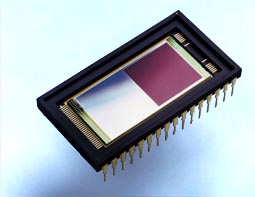
guider camera is an E2V CCD47-20
frame transfer CCD. The array is made up of two sections of 1024×1024 pixels, each
independently clocked. One section is covered with an opaque aluminum
mask. The detector has a split serial register with two output
amplifiers, so it can be read using either output (or both). The device
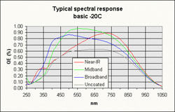
is backside illuminated, with 13 µm square pixels, 80% broadband
quantum efficiency, and less than 3 e- rms readout noise (at
20 kpix/s). The recommended parallel transfer time for the
back-illuminated E2V CCD47 chip is 10 µs, so the frame transfer
time is close to 10 ms.
Another candidate detector is the E2V CCD67, a 256×256 pixel frame transfer device with 26 µm pixels, and an on-chip mask. The smaller format (ie smaller field-of-view) of this device can be traded-off for a faster frame rate.
And, there is also the SITe 1024×1024 pixel, back-illuminated SI-003A device. With an off-chip mask attached to the CCD package, it could be used in frame transfer mode, with a 512×1024 pixel imaging area. The principal limitation of this device is the parallel transfer time (180 µs) which limits the frame rate.The guider camera electronics will support various detector choices without modification. Each different detector is mounted on a custom header board. The characteristics of the three detectors are shown in the table.
| Device Specifications | E2V CCD47 | E2V CCD67 |
SITe SI-003A |
Units |
| Readout Noise | 3 | 3 | 5 | e- |
| Peak Quantum Efficiency | >80 | >80 | >80 | % |
| Array size | 2048 × 1024 | 512 × 256 | 1024 × 1024 |
pixels |
| Pixel size | 13 | 26 | 24 | µm |
| Amplifiers | 2 | 2 | 2 | |
| Dark current | 250 | 1000 | 700 | e-/pix/s |
Greg Burley (burley@obs.carnegiescience.edu)
Ian Thompson (ian@obs.carnegiescience.edu)
