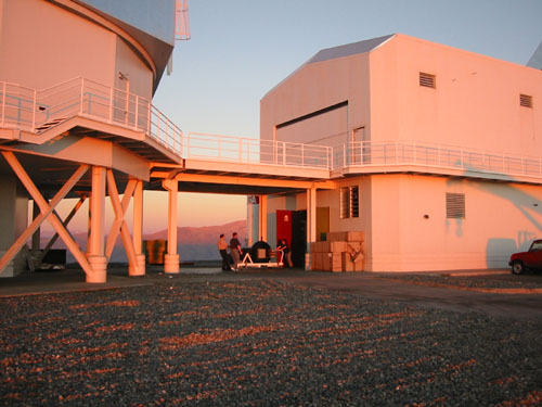
 Each
MIKE
CCD detector system uses a 2K × 4K back-illuminated device,
with 15 µm pixels and two output amplifiers.
 At present, the red channel uses a deep depletion E2V CCD44-82 device with a red-enhanced anti-reflection coating, while the blue channel uses a standard E2V CCD44-82 with a broadband-astronomy coating.
Previously, the red channel used a SITe ST-002A CCD with a standard broadband coating, while the blue channel used a MIT Lincoln Labs CCID-20 with a blue enhanced coating.
Each detector is mounted in a rectangular aluminum housing. The dewar window on each side is the field flattener of the camera.
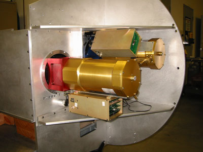
The CCD housing is coupled to an IR-Labs ND-5 cryostat, with the CCD control electronics box attached to the side of the dewar (see photo). Each CCD is liquid nitrogen cooled and has roughly 15 hour hold time in the horizontal position. Inside the housing, the CCD is connnected to a rigid-flex preamp board, which brings the signals out on a flex cable to a hermetic connector.
Each CCD controller is a compact dual-channel digital signal processor based system, capable of both high-speed and slow-scan readout. We plan to operate in slow-scan mode, using only the better of the two CCD output amplifiers for the lowest noise performance. Lab tests show that read noise is about 2.5 e- for both E2V devices. With the previous detectors, the read noise was about 4 e- for the SITe device and 1.8 e- for the LL device. The two detector systems are mounted side-by-side on the instrument (see photo) and operate independently. That is, they have independent shutters, exposure times and readout times.
[from R. Bernstein et al, "MIKE: A double-echelle spectrograph for the Magellan telescopes at Las Campanas Observatory," SPIE 4841 Astronomical Telescopes and Instrumentation, Kona (2002).]
| Device Specifications | CCD44-82 |
ST-002A |
CCID-20 |
Units |
| Peak Quantum Efficiency | >80 |
>80 | >90 |
% |
| Array size | 2048 × 4096 |
2048
× 4096 |
2048
× 4096 |
pixels |
| Pixel size | 15 |
15 |
15 |
µm |
| Amplifiers | 2 |
2 | 2 |
|
| Full well |
>150 |
>60 |
20 |
ke- |
| Dark
current
(at -125 °C) |
<1 |
<
1 |
3.6 |
e-/pix/hr |
| Read noise |
2.5 |
3.5 | 1.8 | e- |
CCD Quantum
efficiency measurements
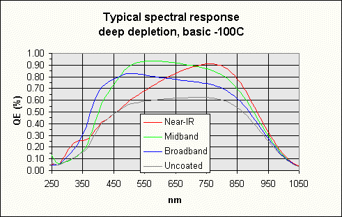 E2V QE curve -- current MIKE detectors |
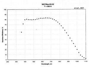 SITe QE curve -- original MIKE detectors.
|
Dewar Mechanical Internals
The CCD housing for the MIKE detectors is machined from a block of aluminum, and measures 6.625 inches x 6.625 inches x 5 inches deep (see mechanical drawings).
Both the MIKE-RED and the MIKE-BLUE detectors are mounted on Invar platens. Connection to the detector is via a zero-insertion force 40-pin connector, with a flex cable to the 37-pin micro-D preamp connector. Two of the previous MIKE detectors are also shown in the photos.
The Invar baseplate is supported on three G-10 standoffs which provide thermal isolation and permit the ccd tilt to be adjusted. The G-10 standoffs are screwed into the base of the dewar head.
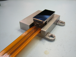 E2V 2048 x 4096 CCD |
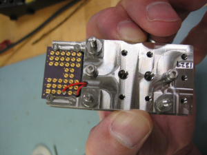 E2V CCD back |
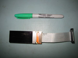 SITe 2048 × 4096 CCD |
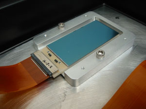 MIT/LL 2048 × 4096 CCID-20 |
One side of the dewar head has a recessed sideplate (with o-ring) where we mount a preamplifier rigid-flex circuit board. The component area of the pcb is rigid, and has a flex cable which solders to the 79-pin connector. The internal board has two preamp circuits, filters for the clock and bias lines, and two temperature sensor circuits.
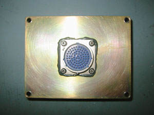 Hermetic 79-pin connector |
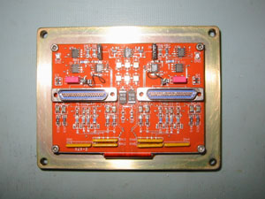 Rigid-flex preamp board |
The cold probe from the dewar cold surface contacts the ccd+boat from underneath. A small temperature sensor and heater resistor are fitted to the bottom of the platen to stabilize the temperature.
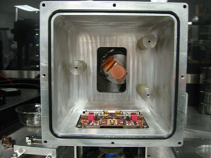 Dewar head with preamp and cooling strap |
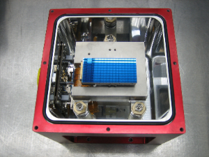 CCD installed in dewar head |
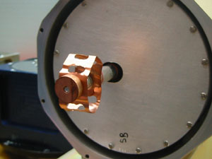 Cold post and spring-loaded copper strap |
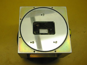 Back o-ring surface |
Test results -- Known Issues
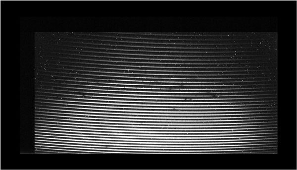 Sample MIKE blue output -- OBJ CS2945-017 1800 sec binned 2x2 [.fits] |
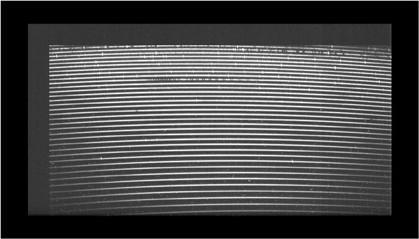 Sample MIKE red output -- OBJ CS2945-017 1800 sec binned 2x2 [.fits] |
| Mode | Pixel
time |
Gain | Noise |
Readout
(1×1) |
Readout
(2×2) |
| (µsec) |
(e-/DN) | (
e- ) |
(sec) |
(
sec ) |
|
| Red (fast) | 9 |
-- | 3.1 |
85 |
28 |
| Red (slow) | 16 |
-- | 2.6 |
155 |
48 |
| Blue (fast) | 9 |
-- | 3.1 |
85 |
28 |
| Blue (slow) | 14 |
-- | 2.6 |
130 |
40 |
Greg Burley (burley@obs.carnegiescience.edu)
Ian Thompson (ian@obs.carnegiescience.edu)
